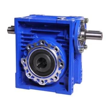
Product Description
Product Parameters
Editing and broadcasting of main materials
1. Body, die-casting aluminum alloy;
2. Worm shaft, 20 Crq steel, high temperature treatment;
3. Worm gear, nickel bronze alloy;
4. Aluminum alloy body, sandblasting and surface anti-corrosion treatment;
5. Cast iron body, painted with bIu RA5571.
Regular center distance specification editing and broadcasting
Center distance: 130 (unit: mm).
Output hole/shaft diameter: 11, 14, 18, 25, 28, 35, 42, 45 (unit: mm)
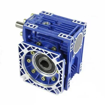
Detailed Photos
|
NMRV-063-30-VS–AS-80B5-0.75KW-B3 |
|||
|
NMRV |
Means hole-input with flange |
||
|
NRV |
Means shaft-input without flange |
||
|
063 |
Centre-to-centre spacing of worm-gear speed reducer |
||
|
30 |
ratio |
||
|
VS |
Double input shaft |
F1(FA) |
Flange putput shaft |
|
AS |
Single output shaft |
AB |
Double output shaft |
|
PAM |
|
80B5 |
Motor mounting facility |
|
0.75KW |
|
B3 |
Mounting position |
|
N2 |
NRV571 |
NRV030 |
NRV040 |
NRV050 |
NRV063 |
NRV075 |
NRV090 |
NRV110 |
NRV130 |
|
400 |
390 |
530 |
1571 |
1400 |
1830 |
2160 |
2390 |
3571 |
3950 |
|
250 |
460 |
620 |
1200 |
1650 |
2150 |
2520 |
2800 |
3530 |
4610 |
|
150 |
550 |
740 |
1420 |
1960 |
2450 |
2990 |
3310 |
4180 |
5470 |
|
100 |
630 |
850 |
1620 |
2250 |
2910 |
3430 |
3800 |
4790 |
6260 |
|
60 |
740 |
1000 |
1920 |
2660 |
3450 |
4060 |
4500 |
5680 |
7420 |
|
40 |
850 |
1150 |
2200 |
3050 |
3950 |
4650 |
5150 |
6500 |
8500 |
|
25 |
990 |
1350 |
2570 |
3570 |
4620 |
5440 |
6571 |
7600 |
9940 |
|
10 |
1350 |
1830 |
3490 |
4840 |
6270 |
7380 |
8180 |
10320 |
13500 |
|
|
|
|
|
|
|
|
|
|
|
|
A |
50 |
65 |
84 |
101 |
120 |
131 |
162 |
191 |
203 |
|
B |
38 |
50 |
64 |
76 |
95 |
101 |
122 |
151 |
163 |
Use and safety guarantee
1. Please check and confirm the matching intensity between worm gear reducer and mechanical equipment before use to assure that it is in the safety range of worm gear reducer performance parameters
2. Worm gear reducer has filled with WA460 lubricating oil. Please replace the lubricating oil after the first starting of 400 hours and after then 4000 hours for lubricating oil replacing cycle
3. There should be enough lubrication in worm gear box and keep regular check with the oil level.
4. When installation. please be careful to avoid sharp instruments bruising the oil seals on output shaft to cause leakage
5. Please confirm the rotation direction before mechanical connection. If the rotation direction is not correct, it will possible injury or damage the devices
6. Please set safety covers in rotating position to avoid of injuring
7. Please pay full attention: it is very dangerous if there is off or falling when movin
/* January 22, 2571 19:08:37 */!function(){function s(e,r){var a,o={};try{e&&e.split(“,”).forEach(function(e,t){e&&(a=e.match(/(.*?):(.*)$/))&&1
| Hardness: | Hardened Tooth Surface |
|---|---|
| Installation: | 90 Degree |
| Layout: | Expansion |
| Gear Shape: | Bevel Gear |
| Step: | Single-Step |
| Type: | Gear Reducer |
| Samples: |
US$ 30/Piece
1 Piece(Min.Order) | |
|---|
Can a Worm Gearbox be Used for High-Speed Applications?
Worm gearboxes are generally not recommended for high-speed applications due to their inherent design characteristics. Here’s why:
- Efficiency: Worm gearboxes tend to have lower efficiency compared to other gearbox types, which means they can generate more heat and experience more energy loss at high speeds.
- Heat Generation: The sliding contact between the worm and worm wheel in a worm gearbox can lead to significant friction and heat generation, especially at high speeds. This heat can cause thermal expansion, affecting the gearbox’s performance and longevity.
- Wear and Noise: High speeds can exacerbate wear and noise issues in worm gearboxes. Increased friction and wear can lead to faster degradation of components, resulting in reduced lifespan and increased maintenance needs.
- Backlash: Worm gearboxes may have higher backlash compared to other gearbox types, which can impact precision and accuracy in high-speed applications.
While worm gearboxes are more commonly used in applications requiring high torque and moderate speeds, they may not be the best choice for high-speed scenarios. If high-speed operation is a requirement, other gearbox types such as helical, spur, or planetary gearboxes are often better suited due to their higher efficiency, lower heat generation, and reduced wear at elevated speeds.

Worm Gearboxes in Conveyor Systems: Benefits and Considerations
Worm gearboxes play a crucial role in conveyor systems, offering several benefits and considerations for their effective integration:
- Space Efficiency: Worm gearboxes have a compact design, making them suitable for applications with limited space, such as conveyor systems.
- High Reduction Ratios: Worm gearboxes can achieve high reduction ratios in a single stage, allowing for slower conveyor speeds without sacrificing torque.
- Self-Locking: Worm gearboxes have inherent self-locking properties, preventing the conveyor from moving when the motor is not actively driving it.
- Directional Control: Worm gearboxes facilitate directional control, enabling the conveyor to move forward or reverse as needed.
- Low Noise: Worm gearboxes often produce lower noise levels compared to other gearbox types, contributing to quieter conveyor operation.
However, there are also considerations to keep in mind when using worm gearboxes in conveyor systems:
- Efficiency: Worm gearboxes may have lower mechanical efficiency compared to some other gearbox types, leading to energy losses.
- Heat Generation: Worm gearboxes can generate more heat due to sliding contact between the worm and gear, necessitating proper cooling mechanisms.
- Lubrication: Proper lubrication is critical to prevent wear and ensure efficient operation. Regular maintenance is required to monitor lubrication levels.
- Load and Speed: Worm gearboxes are well-suited for applications with high torque and low to moderate speed requirements. They may not be optimal for high-speed conveyors.
Before integrating a worm gearbox into a conveyor system, it’s important to carefully consider the specific requirements of the application, including load, speed, space constraints, and efficiency needs. Consulting with gearbox experts and manufacturers can help ensure the right choice for the conveyor’s performance and longevity.

Advantages of Using a Worm Reducer in Mechanical Systems
Worm reducers offer several advantages that make them suitable for various mechanical systems:
- High Gear Reduction Ratio: Worm gearboxes provide significant speed reduction, making them ideal for applications that require a high gear reduction ratio without the need for multiple gears.
- Compact Design: Worm reducers have a compact and space-saving design, allowing them to be used in applications with limited space.
- Self-Locking: Worm gearboxes exhibit self-locking properties, which means that the worm screw can prevent the worm wheel from reversing its motion. This is beneficial for applications where the gearbox needs to hold a load in place without external braking mechanisms.
- Smooth and Quiet Operation: Worm gearboxes operate with a sliding motion between the teeth, resulting in smoother and quieter operation compared to some other types of gearboxes.
- High Torque Transmission: Worm gearboxes can transmit high torque levels, making them suitable for applications that require powerful torque output.
- Heat Dissipation: The sliding action between the worm screw and the worm wheel contributes to heat dissipation, which can be advantageous in applications that generate heat during operation.
- Stable Performance: Worm reducers offer stable and reliable performance, making them suitable for continuous operation in various industrial and mechanical systems.
Despite these advantages, it’s important to note that worm gearboxes also have limitations, such as lower efficiency compared to other gear types due to the sliding motion and potential for higher heat generation. Therefore, selecting the appropriate type of gearbox depends on the specific requirements and constraints of the application.


editor by CX 2024-04-03
China Professional DC Motor Worm Gearbox for Substitude for Motovario Gearbox Speed Reducer Helical Geared Motor Reducer Smrv Driver Gearbox Speed Reducer Gear Reducer synchromesh gearbox
Product Description
Features
1.Wide transmission rate, strong output torque
2.Compact mechanical structure, light weight, small volume&Good heat-dissipating
3.Smooth operation with lower noise or vibration
4.Easy mounting, free linking, high efficiency
5. PERFECT SUBSTITUDE FOR MOTOVARIO AND CHINAMFG PRODUCTS
Applications
Wide range of application,including light industry of food &beverage, Cement,
package,construction material,chemicals and etc.
Technical data:
| Model | RV 130 150 |
| Single unit versions | NMRV – fitted for motor flanged coupling, NRV – with input shaft, NMRV-E motor flanged coupling with worm extension shaft, NRV-E with double extension worm shaft, |
| Power | 0.06—-15KW |
| Single unit reduction ratio | 1:5 7.5 80 100 |
| Output torque | 2.6—1195N.M |
| Worm shaft material | 20CrMnTi with carburizing and quenching.The hardness of surface is 56-62HRC with carbonized layer 0.5-0.8mm |
| Worm wheel material | worm mandrel is HT250,and worm ring gear,ZQSn10-1,hardness is 60HRC |
After-sale service:
One year warranty,subject to proper operation and installation;free technical support all the time.
| Application: | Motor |
|---|---|
| Hardness: | Hardened |
| Type: | Worm and Wormwheel |
| Samples: |
US$ 35/Piece
1 Piece(Min.Order) | Order Sample |
|---|
| Customization: |
Available
| Customized Request |
|---|
.shipping-cost-tm .tm-status-off{background: none;padding:0;color: #1470cc}
| Shipping Cost:
Estimated freight per unit. |
about shipping cost and estimated delivery time. |
|---|
| Payment Method: |
|
|---|---|
|
Initial Payment Full Payment |
| Currency: | US$ |
|---|
| Return&refunds: | You can apply for a refund up to 30 days after receipt of the products. |
|---|
Common Problems and Troubleshooting for Worm Gearboxes
Worm gearboxes, like any mechanical component, can experience various issues over time. Here are some common problems that may arise and possible troubleshooting steps:
- Overheating: Overheating can occur due to factors such as inadequate lubrication, excessive loads, or high operating temperatures. Check lubrication levels, ensure proper ventilation, and reduce loads if necessary.
- Noise and Vibration: Excessive noise and vibration may result from misalignment, worn gears, or improper meshing. Check for misalignment, inspect gear teeth for wear, and ensure proper gear meshing.
- Leakage: Oil leakage can be caused by damaged seals or gaskets. Inspect seals and gaskets, and replace them if necessary.
- Reduced Efficiency: Efficiency loss can occur due to friction, wear, or misalignment. Regularly monitor gearbox performance, ensure proper lubrication, and address any wear or misalignment issues.
- Backlash: Excessive backlash can affect precision and accuracy. Adjust gear meshing and reduce backlash to improve performance.
- Seizure or Binding: Seizure or binding can result from inadequate lubrication, debris, or misalignment. Clean the gearbox, ensure proper lubrication, and address misalignment issues.
- Worn Gears: Worn gear teeth can lead to poor performance. Regularly inspect gears for signs of wear, and replace worn gears as needed.
- Seal Wear: Seals can wear over time, leading to leakage and contamination. Inspect seals regularly and replace them if necessary.
If you encounter any of these problems, it’s important to address them promptly to prevent further damage and maintain the performance of your worm gearbox. Regular maintenance, proper lubrication, and addressing issues early can help extend the lifespan and reliability of the gearbox.

Worm Gearbox Applications in Robotics and Automation
Worm gearboxes play a crucial role in various robotics and automation applications due to their unique characteristics and benefits. Here are some common applications where worm gearboxes are used:
- Robotic Arm Movement: Worm gearboxes are employed in robotic arms to provide precise and controlled movement. The self-locking property of worm gearboxes helps maintain the arm’s position without requiring additional brakes.
- Conveyor Systems: In automated production lines, worm gearboxes are used to drive conveyor belts and move materials or products along assembly lines with accuracy.
- Precision Positioning: Worm gearboxes are used in precision positioning systems, such as those found in pick-and-place robots and CNC machines. They ensure accurate and repeatable movements.
- Pan and Tilt Mechanisms: Worm gearboxes are utilized in pan and tilt mechanisms of surveillance cameras, robotic cameras, and sensors. The self-locking feature helps stabilize and maintain the desired angle.
- Automated Gates and Doors: Worm gearboxes are used in automated gate and door systems to control their opening and closing movements smoothly and safely.
- Material Handling: Robots in warehouses and distribution centers use worm gearboxes to manipulate and lift objects, enhancing efficiency in material handling.
- Medical Robotics: Worm gearboxes are employed in medical robots for surgical procedures, diagnostic equipment, and rehabilitation devices, ensuring precise and controlled movements.
- Industrial Robots: Industrial robots rely on worm gearboxes for various tasks, including welding, painting, assembly, and packaging, where precise movements are essential.
- Automated Testing Equipment: In testing and inspection applications, worm gearboxes provide the necessary movement and positioning for accurate testing and measurements.
- Food and Beverage Industry: Worm gearboxes are used in automated food processing and packaging systems, ensuring hygienic and precise movement of products.
Worm gearboxes are preferred in these applications due to their compact size, high torque output, self-locking feature, and ability to provide a right-angle drive. However, selecting the right gearbox requires considering factors such as load, speed, efficiency, and environmental conditions.
Can a Worm Gearbox Provide High Torque Output?
Yes, a worm gearbox is capable of providing high torque output due to its unique design and principle of operation. Worm gears are known for their high torque multiplication capabilities, making them suitable for applications that require significant torque transfer.
The torque output of a worm gearbox is influenced by several factors:
- Lead Angle: The lead angle of the worm affects the mechanical advantage of the gear system. A larger lead angle can result in higher torque output.
- Worm Diameter: A larger diameter worm can offer increased torque output as it provides more contact area with the gear.
- Gear Ratio: The gear ratio between the worm and the gear determines the torque multiplication factor. A higher gear ratio leads to higher torque output.
- Lubrication: Proper lubrication is essential to minimize friction and ensure efficient torque transmission.
- Material and Quality: High-quality materials and precision manufacturing contribute to the gearbox’s ability to handle high torque loads.
Due to their ability to provide high torque output in a compact form factor, worm gearboxes are commonly used in various industrial applications, including heavy machinery, construction equipment, conveyor systems, and more.
editor by CX 2023-10-12
China supplier Equivalent to Motovario RV Series Right Angle Worm Gearbox supplier
Product Description
Product Description
Main Materials:
1)housing:aluminium alloy ADC12(size 571-090); die cast iron HT200(size 110-150);
2)Worm:20Cr, ZI Involute profile; carbonize&quencher heat treatment make gear surface hardness up to 56-62 HRC; After precision grinding, carburization layer’s thickness between 0.3-0.5mm.
3)Worm Wheel:wearable stannum alloy CuSn10-1
Detailed Photos
Combination Options:
Input:with input shaft, With square flange,With IEC standard input flange
Output:with torque arm, output flange, single output shaft, double output shaft, plastic cover
Worm reducers are available with diffferent combinations: NMRV+NMRV, NMRV+NRV, NMRV+PC, NMRV+UDL, NMRV+MOTORS
Exploded View:
Product Parameters
| Old Model |
New Model | Ratio | Center Distance | Power | Input Dia. | Output Dia. | Output Torque | Weight |
| RV571 | 7.5~100 | 25mm | 0.06KW~0.12KW | Φ9 | Φ11 | 21N.m | 0.7kgs | |
| RV030 | RW030 | 7.5~100 | 30mm | 0.06KW~0.25KW | Φ9(Φ11) | Φ14 | 45N.m | 1.2kgs |
| RV040 | RW040 | 7.5~100 | 40mm | 0.09KW~0.55KW | Φ9(Φ11,Φ14) | Φ18(Φ19) | 84N.m | 2.3kgs |
| RV050 | RW050 | 7.5~100 | 50mm | 0.12KW~1.5KW | Φ11(Φ14,Φ19) | Φ25(Φ24) | 160N.m | 3.5kgs |
| RV063 | RW063 | 7.5~100 | 63mm | 0.18KW~2.2KW | Φ14(Φ19,Φ24) | Φ25(Φ28) | 230N.m | 6.2kgs |
| RV075 | RW075 | 7.5~100 | 75mm | 0.25KW~4.0KW | Φ14(Φ19,Φ24,Φ28) | Φ28(Φ35) | 410N.m | 9.0kgs |
| RV090 | RW090 | 7.5~100 | 90mm | 0.37KW~4.0KW | Φ19(Φ24,Φ28) | Φ35(Φ38) | 725N.m | 13.0kgs |
| RV110 | RW110 | 7.5~100 | 110mm | 0.55KW~7.5KW | Φ19(Φ24,Φ28,Φ38) | Φ42 | 1050N.m | 35.0kgs |
| RV130 | RW130 | 7.5~100 | 130mm | 0.75KW~7.5KW | Φ24(Φ28,Φ38) | Φ45 | 1550N.m | 48.0kgs |
| RV150 | RW150 | 7.5~100 | 150mm | 2.2KW~15KW | Φ28(Φ38,Φ42) | Φ50 | 84.0kgs |
GMRV Outline Dimension:
| GMRV | A | B | C | C1 | D(H8) | E(h8) | F | G | G1 | H | H1 | I | M | N | O | P | Q | R | S | T | BL | β | b | t | V |
| 030 | 80 | 97 | 54 | 44 | 14 | 55 | 32 | 56 | 63 | 65 | 29 | 55 | 40 | 57 | 30 | 75 | 44 | 6.5 | 21 | 5.5 | M6*10(n=4) | 0° | 5 | 16.3 | 27 |
| 040 | 100 | 121.5 | 70 | 60 | 18(19) | 60 | 43 | 71 | 78 | 75 | 36.5 | 70 | 50 | 71.5 | 40 | 87 | 55 | 6.5 | 26 | 6.5 | M6*10(n=4) | 45° | 6 | 20.8(21.8) | 35 |
| 050 | 120 | 144 | 80 | 70 | 25(24) | 70 | 49 | 85 | 92 | 85 | 43.5 | 80 | 60 | 84 | 50 | 100 | 64 | 8.5 | 30 | 7 | M8*12(n=4) | 45° | 8 | 28.3(27.3) | 40 |
| 063 | 144 | 174 | 100 | 85 | 25(28) | 80 | 67 | 103 | 112 | 95 | 53 | 95 | 72 | 102 | 63 | 110 | 80 | 8.5 | 36 | 8 | M8*12(n=8) | 45° | 8 | 28.3(31.3) | 50 |
| 075 | 172 | 205 | 120 | 90 | 28(35) | 95 | 72 | 112 | 120 | 115 | 57 | 112.5 | 86 | 119 | 75 | 140 | 93 | 11 | 40 | 10 | M8*14(n=8) | 45° | 8(10) | 31.3(38.3) | 60 |
| 090 | 206 | 238 | 140 | 100 | 35(38) | 110 | 74 | 130 | 140 | 130 | 67 | 129.5 | 103 | 135 | 90 | 160 | 102 | 13 | 45 | 11 | M10*16(n=8) | 45° | 10 | 38.3(41.3) | 70 |
| 110 | 255 | 295 | 170 | 115 | 42 | 130 | – | 144 | 155 | 165 | 74 | 160 | 127.5 | 167.5 | 110 | 200 | 125 | 14 | 50 | 14 | M10*18(n=8) | 45° | 12 | 45.3 | 85 |
| 130 | 293 | 335 | 200 | 120 | 45 | 180 | – | 155 | 170 | 215 | 81 | 179 | 146.5 | 187.5 | 130 | 250 | 140 | 16 | 60 | 15 | M12*20(n=8) | 45° | 14 | 48.8 | 100 |
| 150 | 340 | 400 | 240 | 145 | 50 | 180 | – | 185 | 200 | 215 | 96 | 210 | 170 | 230 | 150 | 250 | 180 | 18 | 72.5 | 18 | M12*22(n=8) | 45° | 14 | 53.8 | 120 |
Company Profile
About CHINAMFG Transmission:
We are a professional reducer manufacturer located in HangZhou, ZHangZhoug province.
Our leading products is full range of RV571-150 worm reducers , also supplied GKM hypoid helical gearbox, GRC inline helical gearbox, PC units, UDL Variators and AC Motors, G3 helical gear motor.
Products are widely used for applications such as: foodstuffs, ceramics, packing, chemicals, pharmacy, plastics, paper-making, construction machinery, metallurgic mine, environmental protection engineering, and all kinds of automatic lines, and assembly lines.
With fast delivery, superior after-sales service, advanced producing facility, our products sell well both at home and abroad. We have exported our reducers to Southeast Asia, Eastern Europe and Middle East and so on.Our aim is to develop and innovate on basis of high quality, and create a good reputation for reducers.
Packing information:Plastic Bags+Cartons+Wooden Cases , or on request
We participate Germany Hannver Exhibition-ZheJiang PTC Fair-Turkey Win Eurasia
Logistics
After Sales Service
1.Maintenance Time and Warranty:Within 1 year after receiving goods.
2.Other Service: Including modeling selection guide, installation guide, and problem resolution guide, etc.
FAQ
1.Q:Can you make as per customer drawing?
A: Yes, we offer customized service for customers accordingly. We can use customer’s nameplate for gearboxes.
2.Q:What is your terms of payment ?
A: 30% deposit before production,balance T/T before delivery.
3.Q:Are you a trading company or manufacturer?
A:We are a manufacurer with advanced equipment and experienced workers.
4.Q:What’s your production capacity?
A:8000-9000 PCS/MONTH
5.Q:Free sample is available or not?
A:Yes, we can supply free sample if customer agree to pay for the courier cost
6.Q:Do you have any certificate?
A:Yes, we have CE certificate and SGS certificate report.
Contact information:
Ms Lingel Pan
For any questions just feel free ton contact me. Many thanks for your kind attention to our company!
| Application: | Motor, Machinery, Marine, Agricultural Machinery, Industry |
|---|---|
| Function: | Distribution Power, Change Drive Torque, Speed Changing, Speed Reduction |
| Layout: | Right Angle |
| Hardness: | Hardened Tooth Surface |
| Installation: | Horizontal Type |
| Step: | Double-Step |
| Samples: |
US$ 10/Piece
1 Piece(Min.Order) | |
|---|
| Customization: |
Available
| Customized Request |
|---|

Self-Locking Properties in a Worm Gearbox
Yes, worm gearboxes exhibit self-locking properties, which can be advantageous in certain applications. Self-locking refers to the ability of a mechanism to prevent the transmission of motion from the output shaft back to the input shaft when the system is at rest. Worm gearboxes inherently possess self-locking properties due to the unique design of the worm gear and worm wheel.
The self-locking behavior arises from the angle of the helix on the worm shaft. In a properly designed worm gearbox, the helix angle of the worm is such that it creates a mechanical advantage that resists reverse motion. When the gearbox is not actively driven, the friction between the worm threads and the worm wheel teeth creates a locking effect.
This self-locking feature makes worm gearboxes particularly useful in applications where holding a load in position without external power is necessary. For instance, they are commonly used in situations where there’s a need to prevent a mechanism from backdriving, such as in conveyor systems, hoists, and jacks.
However, it’s important to note that while self-locking properties can be beneficial, they also introduce some challenges. The high friction between the worm gear and worm wheel during self-locking can lead to higher wear and heat generation. Additionally, the self-locking effect can reduce the efficiency of the gearbox when it’s actively transmitting motion.
When considering the use of a worm gearbox for a specific application, it’s crucial to carefully analyze the balance between self-locking capabilities and other performance factors to ensure optimal operation.
Worm Gearbox Applications in Robotics and Automation
Worm gearboxes play a crucial role in various robotics and automation applications due to their unique characteristics and benefits. Here are some common applications where worm gearboxes are used:
- Robotic Arm Movement: Worm gearboxes are employed in robotic arms to provide precise and controlled movement. The self-locking property of worm gearboxes helps maintain the arm’s position without requiring additional brakes.
- Conveyor Systems: In automated production lines, worm gearboxes are used to drive conveyor belts and move materials or products along assembly lines with accuracy.
- Precision Positioning: Worm gearboxes are used in precision positioning systems, such as those found in pick-and-place robots and CNC machines. They ensure accurate and repeatable movements.
- Pan and Tilt Mechanisms: Worm gearboxes are utilized in pan and tilt mechanisms of surveillance cameras, robotic cameras, and sensors. The self-locking feature helps stabilize and maintain the desired angle.
- Automated Gates and Doors: Worm gearboxes are used in automated gate and door systems to control their opening and closing movements smoothly and safely.
- Material Handling: Robots in warehouses and distribution centers use worm gearboxes to manipulate and lift objects, enhancing efficiency in material handling.
- Medical Robotics: Worm gearboxes are employed in medical robots for surgical procedures, diagnostic equipment, and rehabilitation devices, ensuring precise and controlled movements.
- Industrial Robots: Industrial robots rely on worm gearboxes for various tasks, including welding, painting, assembly, and packaging, where precise movements are essential.
- Automated Testing Equipment: In testing and inspection applications, worm gearboxes provide the necessary movement and positioning for accurate testing and measurements.
- Food and Beverage Industry: Worm gearboxes are used in automated food processing and packaging systems, ensuring hygienic and precise movement of products.
Worm gearboxes are preferred in these applications due to their compact size, high torque output, self-locking feature, and ability to provide a right-angle drive. However, selecting the right gearbox requires considering factors such as load, speed, efficiency, and environmental conditions.

Types of Worm Gear Configurations and Their Uses
Worm gear configurations vary based on the arrangement of the worm and the gear it engages with. Here are common types and their applications:
- Single Enveloping Worm Gear: This configuration offers high torque transmission and efficiency. It’s used in heavy-duty applications like mining equipment and industrial machinery.
- Double Enveloping Worm Gear: With increased contact area, this type provides higher load capacity and improved efficiency. It’s used in aerospace applications, robotics, and precision machinery.
- Non-Throated Worm Gear: This type has a cylindrical worm without a throat. It’s suitable for applications requiring precise motion control, such as CNC machines and robotics.
- Throated Worm Gear: Featuring a throat in the worm, this configuration offers smooth engagement and higher load capacity. It’s used in conveyors, elevators, and automotive applications.
- Non-Modular Worm Gear: In this design, the worm and gear are a matched set, resulting in better meshing and efficiency. It’s utilized in various industries where customization is essential.
- Modular Worm Gear: This type allows interchangeability of worm and gear components, providing flexibility in design and maintenance. It’s commonly used in conveyors, mixers, and material handling systems.
Selecting the appropriate worm gear configuration depends on factors such as load capacity, efficiency, precision, and application requirements. Consulting gearbox experts can help determine the best configuration for your specific needs.
editor by CX 2023-09-15
China Professional Motovario Nmrv Worm Gearbox for Variable Gear Transmission planetary gearbox
Product Description
Product Description
Main Materials:
1)housing:aluminium alloy ADC12(size 571-090); die cast iron HT200(size 110-150);
2)Worm:20Cr, ZI Involute profile; carbonize&quencher heat treatment make gear surface hardness up to 56-62 HRC; After precision grinding, carburization layer’s thickness between 0.3-0.5mm.
3)Worm Wheel:wearable stannum alloy CuSn10-1
Detailed Photos
Combination Options:
Input:with input shaft, With square flange,With IEC standard input flange
Output:with torque arm, output flange, single output shaft, double output shaft, plastic cover
Worm reducers are available with diffferent combinations: NMRV+NMRV, NMRV+NRV, NMRV+PC, NMRV+UDL, NMRV+MOTORS
Exploded View:
Product Parameters
| Old Model |
New Model | Ratio | Center Distance | Power | Input Dia. | Output Dia. | Output Torque | Weight |
| RV571 | 7.5~100 | 25mm | 0.06KW~0.12KW | Φ9 | Φ11 | 21N.m | 0.7kgs | |
| RV030 | RW030 | 7.5~100 | 30mm | 0.06KW~0.25KW | Φ9(Φ11) | Φ14 | 45N.m | 1.2kgs |
| RV040 | RW040 | 7.5~100 | 40mm | 0.09KW~0.55KW | Φ9(Φ11,Φ14) | Φ18(Φ19) | 84N.m | 2.3kgs |
| RV050 | RW050 | 7.5~100 | 50mm | 0.12KW~1.5KW | Φ11(Φ14,Φ19) | Φ25(Φ24) | 160N.m | 3.5kgs |
| RV063 | RW063 | 7.5~100 | 63mm | 0.18KW~2.2KW | Φ14(Φ19,Φ24) | Φ25(Φ28) | 230N.m | 6.2kgs |
| RV075 | RW075 | 7.5~100 | 75mm | 0.25KW~4.0KW | Φ14(Φ19,Φ24,Φ28) | Φ28(Φ35) | 410N.m | 9.0kgs |
| RV090 | RW090 | 7.5~100 | 90mm | 0.37KW~4.0KW | Φ19(Φ24,Φ28) | Φ35(Φ38) | 725N.m | 13.0kgs |
| RV110 | RW110 | 7.5~100 | 110mm | 0.55KW~7.5KW | Φ19(Φ24,Φ28,Φ38) | Φ42 | 1050N.m | 35.0kgs |
| RV130 | RW130 | 7.5~100 | 130mm | 0.75KW~7.5KW | Φ24(Φ28,Φ38) | Φ45 | 1550N.m | 48.0kgs |
| RV150 | RW150 | 7.5~100 | 150mm | 2.2KW~15KW | Φ28(Φ38,Φ42) | Φ50 | 84.0kgs |
GMRV Outline Dimension:
| GMRV | A | B | C | C1 | D(H8) | E(h8) | F | G | G1 | H | H1 | I | M | N | O | P | Q | R | S | T | BL | β | b | t | V |
| 030 | 80 | 97 | 54 | 44 | 14 | 55 | 32 | 56 | 63 | 65 | 29 | 55 | 40 | 57 | 30 | 75 | 44 | 6.5 | 21 | 5.5 | M6*10(n=4) | 0° | 5 | 16.3 | 27 |
| 040 | 100 | 121.5 | 70 | 60 | 18(19) | 60 | 43 | 71 | 78 | 75 | 36.5 | 70 | 50 | 71.5 | 40 | 87 | 55 | 6.5 | 26 | 6.5 | M6*10(n=4) | 45° | 6 | 20.8(21.8) | 35 |
| 050 | 120 | 144 | 80 | 70 | 25(24) | 70 | 49 | 85 | 92 | 85 | 43.5 | 80 | 60 | 84 | 50 | 100 | 64 | 8.5 | 30 | 7 | M8*12(n=4) | 45° | 8 | 28.3(27.3) | 40 |
| 063 | 144 | 174 | 100 | 85 | 25(28) | 80 | 67 | 103 | 112 | 95 | 53 | 95 | 72 | 102 | 63 | 110 | 80 | 8.5 | 36 | 8 | M8*12(n=8) | 45° | 8 | 28.3(31.3) | 50 |
| 075 | 172 | 205 | 120 | 90 | 28(35) | 95 | 72 | 112 | 120 | 115 | 57 | 112.5 | 86 | 119 | 75 | 140 | 93 | 11 | 40 | 10 | M8*14(n=8) | 45° | 8(10) | 31.3(38.3) | 60 |
| 090 | 206 | 238 | 140 | 100 | 35(38) | 110 | 74 | 130 | 140 | 130 | 67 | 129.5 | 103 | 135 | 90 | 160 | 102 | 13 | 45 | 11 | M10*16(n=8) | 45° | 10 | 38.3(41.3) | 70 |
| 110 | 255 | 295 | 170 | 115 | 42 | 130 | – | 144 | 155 | 165 | 74 | 160 | 127.5 | 167.5 | 110 | 200 | 125 | 14 | 50 | 14 | M10*18(n=8) | 45° | 12 | 45.3 | 85 |
| 130 | 293 | 335 | 200 | 120 | 45 | 180 | – | 155 | 170 | 215 | 81 | 179 | 146.5 | 187.5 | 130 | 250 | 140 | 16 | 60 | 15 | M12*20(n=8) | 45° | 14 | 48.8 | 100 |
| 150 | 340 | 400 | 240 | 145 | 50 | 180 | – | 185 | 200 | 215 | 96 | 210 | 170 | 230 | 150 | 250 | 180 | 18 | 72.5 | 18 | M12*22(n=8) | 45° | 14 | 53.8 | 120 |
Company Profile
About CZPT Transmission:
We are a professional reducer manufacturer located in HangZhou, ZHangZhoug province.
Our leading products is full range of RV571-150 worm reducers , also supplied GKM hypoid helical gearbox, GRC inline helical gearbox, PC units, UDL Variators and AC Motors, G3 helical gear motor.
Products are widely used for applications such as: foodstuffs, ceramics, packing, chemicals, pharmacy, plastics, paper-making, construction machinery, metallurgic mine, environmental protection engineering, and all kinds of automatic lines, and assembly lines.
With fast delivery, superior after-sales service, advanced producing facility, our products sell well both at home and abroad. We have exported our reducers to Southeast Asia, Eastern Europe and Middle East and so on.Our aim is to develop and innovate on basis of high quality, and create a good reputation for reducers.
Packing information:Plastic Bags+Cartons+Wooden Cases , or on request
We participate Germany Hannver Exhibition-ZheJiang PTC Fair-Turkey Win Eurasia
Logistics
After Sales Service
1.Maintenance Time and Warranty:Within 1 year after receiving goods.
2.Other Service: Including modeling selection guide, installation guide, and problem resolution guide, etc.
FAQ
1.Q:Can you make as per customer drawing?
A: Yes, we offer customized service for customers accordingly. We can use customer’s nameplate for gearboxes.
2.Q:What is your terms of payment ?
A: 30% deposit before production,balance T/T before delivery.
3.Q:Are you a trading company or manufacturer?
A:We are a manufacurer with advanced equipment and experienced workers.
4.Q:What’s your production capacity?
A:8000-9000 PCS/MONTH
5.Q:Free sample is available or not?
A:Yes, we can supply free sample if customer agree to pay for the courier cost
6.Q:Do you have any certificate?
A:Yes, we have CE certificate and SGS certificate report.
Contact information:
Ms Lingel Pan
For any questions just feel free ton contact me. Many thanks for your kind attention to our company!
| Application: | Motor, Machinery, Marine, Agricultural Machinery, Industry |
|---|---|
| Function: | Distribution Power, Change Drive Torque, Speed Changing, Speed Reduction |
| Layout: | Right Angle |
| Hardness: | Hardened Tooth Surface |
| Installation: | Horizontal Type |
| Step: | Double-Step |
| Samples: |
Is it Possible to Reverse the Direction of a Worm Gearbox?Yes, it is possible to reverse the direction of a worm gearbox by changing the orientation of either the input or output shaft. However, reversing the direction of a worm gearbox can have some implications that need to be considered:
If you need to reverse the direction of a worm gearbox, it’s advisable to consult the gearbox manufacturer’s guidelines and recommendations. They can provide insights into whether the specific gearbox model is suitable for reversible operation and any precautions or adjustments needed to ensure proper functioning.
US$ 10/Piece
1 Piece(Min.Order) | |
|---|
| Customization: |
Available
| Customized Request |
|---|
What Industries Commonly Use Worm Reducers?
Worm reducers are versatile mechanical components that find applications in various industries due to their unique advantages and capabilities. Some of the industries that commonly use worm reducers include:
- Material Handling: Worm reducers are widely used in material handling equipment such as conveyors, bucket elevators, and cranes to control movement and manage heavy loads.
- Automotive: They are utilized in automotive manufacturing processes, assembly lines, and vehicle positioning systems.
- Food and Beverage: Worm reducers are used in food processing and packaging machinery where hygiene and cleanliness are crucial.
- Agriculture: Agricultural equipment like irrigation systems and tractors use worm reducers for controlling rotational motion.
- Mining and Construction: Heavy-duty applications in mining equipment, excavators, and construction machinery benefit from the torque multiplication provided by worm reducers.
- Energy: Wind turbines and solar tracking systems use
How to Calculate the Efficiency of a Worm Gearbox
Calculating the efficiency of a worm gearbox involves determining the ratio of output power to input power. Efficiency is a measure of how well the gearbox converts input power into useful output power without losses. Here’s how to calculate it:
- Step 1: Measure Input Power: Measure the input power (Pin) using a power meter or other suitable measuring equipment.
- Step 2: Measure Output Power: Measure the output power (Pout) that the gearbox is delivering to the load.
- Step 3: Calculate Efficiency: Calculate the efficiency (η) using the formula: Efficiency (η) = (Output Power / Input Power) * 100%
For example, if the input power is 1000 watts and the output power is 850 watts, the efficiency would be (850 / 1000) * 100% = 85%.
It’s important to note that efficiencies can vary based on factors such as gear design, lubrication, wear, and load conditions. The calculated efficiency provides insight into how effectively the gearbox is converting power, but it’s always a good practice to refer to manufacturer specifications for gearbox efficiency ratings.
worm reducers to convert low-speed, high-torque motion into rotational energy.
- Textile: Textile machinery employs worm reducers for controlling speed and tension in weaving and spinning operations.
- Packaging: Packaging equipment relies on worm reducers for precise movement and positioning of packaging materials.
- Medical: Medical devices and equipment often utilize worm reducers for their accuracy and controlled motion.
- Printing: Printing machines use worm reducers to regulate paper feed and ensure consistent printing quality.
Worm reducers’ ability to provide high torque output, compact design, and self-locking characteristics makes them suitable for applications requiring reliable and controlled motion across various industries.
editor by CX 2023-09-04
China Nmrv Series 025-150 Worm Gearboxes Same as Motovario Type worm gearbox angle
Product Description
Product Description
Primary Attributes:
1) Produced of large top quality aluminum alloy, light-weight fat and non-rusting
2) Large output torque and higher radiating effectiveness
3) Easy managing and minimal sounds, can function long time in dreadful issue
4) Good-searching physical appearance, resilient support existence and modest volume
five) Appropriate for omnibearing set up
Major Materials:
1)housing:aluminium alloy ADC12(size 571-090) die forged iron HT200(dimensions 110-150)
two)Worm:20Cr, ZI Involute profile carbonize&quencher warmth treatment method make gear surface hardness up to fifty six-62 HRC Following precision grinding, carburization layer’s thickness among .3-.5mm.
three)Worm Wheel:wearable stannum alloy CuSn10-one
Blend Possibilities:
Enter:with input shaft, With sq. flange,With IEC regular input flange
Output:with torque arm, output flange, single output shaft, double output shaft, plastic include
Worm reducers are offered with diffferent combinations: NMRV+NMRV, NMRV+NRV, NMRV+Laptop, NMRV+UDL, NMRV+MOTORS
Detailed Photos
Product Parameters
| Old Model | New Model | Ratio | Center Distance | Power | Input Dia. | Output Dia. | Output Torque | Weight |
| RV571 | 7.5~100 | 25mm | .06KW~.12KW | Φ9 | Φ11 | 21N.m | .7kgs | |
| RV030 | RW030 | seven.5~one hundred | 30mm | .06KW~.25KW | Φ9(Φ11) | Φ14 | 45N.m | one.2kgs |
| RV040 | RW040 | seven.5~a hundred | 40mm | .09KW~.55KW | Φ9(Φ11,Φ14) | Φ18(Φ19) | 84N.m | 2.3kgs |
| RV050 | RW050 | seven.5~100 | 50mm | .12KW~1.5KW | Φ11(Φ14,Φ19) | Φ25(Φ24) | 160N.m | three.5kgs |
| RV063 | RW063 | 7.5~one hundred | 63mm | .18KW~2.2KW | Φ14(Φ19,Φ24) | Φ25(Φ28) | 230N.m | six.2kgs |
| RV075 | RW075 | 7.5~a hundred | 75mm | .25KW~4.0KW | Φ14(Φ19,Φ24,Φ28) | Φ28(Φ35) | 410N.m | nine.0kgs |
| RV090 | RW090 | seven.5~100 | 90mm | .37KW~4.0KW | Φ19(Φ24,Φ28) | Φ35(Φ38) | 725N.m | thirteen.0kgs |
| RV110 | RW110 | seven.5~100 | 110mm | .55KW~7.5KW | Φ19(Φ24,Φ28,Φ38) | Φ42 | 1050N.m | 35.0kgs |
| RV130 | RW130 | 7.5~one hundred | 130mm | .75KW~7.5KW | Φ24(Φ28,Φ38) | Φ45 | 1550N.m | 48.0kgs |
| RV150 | RW150 | seven.5~a hundred | 150mm | 2.2KW~15KW | Φ28(Φ38,Φ42) | Φ50 | 84.0kgs |
Exploded View:
GMRV Outline Dimension:
| GMRV | A | B | C | C1 | D(H8) | E(h8) | F | G | G1 | H | H1 | I | M | N | O | P | Q | R | S | T | BL | β | b | t | V |
| 030 | eighty | ninety seven | 54 | forty four | 14 | 55 | 32 | fifty six | sixty three | 65 | 29 | fifty five | forty | fifty seven | 30 | seventy five | forty four | 6.five | 21 | five.5 | M6*10(n=4) | 0° | 5 | sixteen.3 | 27 |
| 040 | a hundred | 121.5 | 70 | sixty | 18(19) | 60 | 43 | 71 | seventy eight | 75 | 36.five | 70 | 50 | seventy one.5 | 40 | 87 | fifty five | 6.5 | 26 | 6.five | M6*10(n=4) | 45° | 6 | twenty.8(21.8) | 35 |
| 050 | a hundred and twenty | 144 | 80 | 70 | twenty five(24) | 70 | 49 | 85 | ninety two | 85 | forty three.five | 80 | sixty | 84 | 50 | a hundred | 64 | 8.5 | 30 | seven | M8*12(n=4) | 45° | eight | 28.3(27.3) | 40 |
| 063 | a hundred and forty four | 174 | one hundred | 85 | 25(28) | 80 | 67 | 103 | 112 | ninety five | 53 | ninety five | 72 | 102 | sixty three | a hundred and ten | 80 | eight.five | 36 | eight | M8*12(n=8) | 45° | eight | 28.3(31.3) | fifty |
| 075 | 172 | 205 | one hundred twenty | 90 | 28(35) | ninety five | 72 | 112 | a hundred and twenty | a hundred and fifteen | 57 | 112.5 | 86 | 119 | 75 | 140 | ninety three | 11 | 40 | ten | M8*14(n=8) | 45° | eight(10) | 31.3(38.3) | sixty |
| 090 | 206 | 238 | 140 | one hundred | 35(38) | 110 | seventy four | 130 | 140 | 130 | sixty seven | 129.5 | 103 | a hundred thirty five | ninety | 160 | 102 | 13 | forty five | 11 | M10*16(n=8) | 45° | 10 | 38.3(41.3) | 70 |
| a hundred and ten | 255 | 295 | 170 | 115 | 42 | 130 | – | a hundred and forty four | 155 | 165 | seventy four | one hundred sixty | 127.5 | 167.five | 110 | two hundred | a hundred twenty five | fourteen | fifty | 14 | M10*18(n=8) | 45° | twelve | 45.three | 85 |
| 130 | 293 | 335 | 200 | one hundred twenty | forty five | one hundred eighty | – | one hundred fifty five | one hundred seventy | 215 | 81 | 179 | 146.five | 187.five | one hundred thirty | 250 | a hundred and forty | sixteen | 60 | fifteen | M12*20(n=8) | 45° | fourteen | 48.eight | a hundred |
| one hundred fifty | 340 | 400 | 240 | a hundred forty five | fifty | 180 | – | 185 | 200 | 215 | 96 | 210 | one hundred seventy | 230 | one hundred fifty | 250 | a hundred and eighty | 18 | 72.5 | 18 | M12*22(n=8) | 45° | 14 | fifty three.8 | 120 |
Firm Profile
About CZPT Transmission:
We are a professional reducer producer situated in HangZhou, ZHangZhoug province.
Our foremost goods is full range of RV571-150 worm reducers , also supplied GKM hypoid helical gearbox, GRC inline helical gearbox, Personal computer units, UDL Variators and AC Motors, G3 helical gear motor.
Merchandise are widely utilised for purposes this sort of as: foodstuffs, ceramics, packing, chemicals, pharmacy, plastics, paper-making, building machinery, metallurgic mine, environmental safety engineering, and all types of automatic lines, and assembly strains.
With quick delivery, superior after-sales services, innovative creating facility, our merchandise promote well both at home and abroad. We have exported our reducers to Southeast Asia, Japanese Europe and the Middle East and so on.Our aim is to create and innovate on the basis of high top quality, and produce a good status for reducers.
Workshop:
Exhibitions:
We participate Germany Hannver Exhibition-ZheJiang PTC Truthful-Turkey Win Eurasia
Packaging & Transport
Packing data:Plastic Bags+Cartons+Wooden Circumstances , or on ask for
Set up Recommendations
To install the reducer, it is essential to notice the adhering to issues:
1)Verify the right rotation path of output shaft ahead of fitting reducer to equipment.
two)Just before mounting, pls check shaft diameter, bore diameter, crucial and keyway, to be confident their dimension are not deviation In get to hold excellent performance, also pls avoid assembling way too tight or also unfastened.
3)Reducer have to be mounted to devices stably to avoid vibration.
4)Every time attainable,safeguard the reducer in opposition to solar radiation and poor weather.
five)In the circumstance of especially lengthy period of time of storage(4-6 months), if the oil seal is not immersed in lubricant within the device, it is advised to alter it because the rubber could adhere to the shaft or may possibly even have missing the elasticity.
six)Portray should absolutely not go in excess of rubber elements and the holes on breather plug if any.
7)When hook up with hollow or solid shaft, pls grease the joint to stay away from lock or oxidation.
8)Examine the right lubricant stage through indicator if there is a single.
9)Starting should take area slowly, with no quickly implementing the highest load.
ten)When using different of motors to match reducer directly, supporting unit is necessary if motor is also weighty.
eleven)Make sure good heat dissipation by maintaining great air flow close to the motor fan.
twelve)In the situation of ambient temperature40ºC, pls get in touch with the technical section.
Soon after Income Support
one.Routine maintenance Time and Warranty:Inside of 1 calendar year right after getting items.
two.Other Provider: Which includes modeling variety guide, installation manual, and dilemma resolution information, etc.
FAQ
one.Q:Can you make as for every client drawing?
A: Yes, we provide customized provider for consumers accordingly. We can use customer’s nameplate for gearboxes.
2.Q:What is your conditions of payment ?
A: thirty% deposit prior to production,equilibrium T/T prior to shipping and delivery.
three.Q:Are you a trading company or maker?
A:We are a manufacurer with sophisticated tools and seasoned staff.
four.Q:What’s your manufacturing capacity?
A:8000-9000 PCS/Month
five.Q:Totally free sample is available or not?
A:Indeed, we can supply free sample if customer agree to pay for the courier price
6.Q:Do you have any certification?
A:Yes, we have CE certification and SGS certification report.
Get in touch with data:
Ms Lingel Pan
For any queries just really feel free ton get in touch with me. Several many thanks for your variety focus to our firm!
|
US $10-220 / Piece | |
1 Piece (Min. Order) |
###
| Application: | Motor, Machinery, Marine, Agricultural Machinery, Industry |
|---|---|
| Hardness: | Hardened Tooth Surface |
| Installation: | Horizontal Type |
| Layout: | Right Angle |
| Gear Shape: | Worm Gear |
| Step: | Double-Step |
###
| Samples: |
US$ 22/Piece
1 Piece(Min.Order) |
|---|
###
| Customization: |
Available
|
|---|
###
| Old Model | New Model | Ratio | Center Distance | Power | Input Dia. | Output Dia. | Output Torque | Weight |
| RV025 | 7.5~100 | 25mm | 0.06KW~0.12KW | Φ9 | Φ11 | 21N.m | 0.7kgs | |
| RV030 | RW030 | 7.5~100 | 30mm | 0.06KW~0.25KW | Φ9(Φ11) | Φ14 | 45N.m | 1.2kgs |
| RV040 | RW040 | 7.5~100 | 40mm | 0.09KW~0.55KW | Φ9(Φ11,Φ14) | Φ18(Φ19) | 84N.m | 2.3kgs |
| RV050 | RW050 | 7.5~100 | 50mm | 0.12KW~1.5KW | Φ11(Φ14,Φ19) | Φ25(Φ24) | 160N.m | 3.5kgs |
| RV063 | RW063 | 7.5~100 | 63mm | 0.18KW~2.2KW | Φ14(Φ19,Φ24) | Φ25(Φ28) | 230N.m | 6.2kgs |
| RV075 | RW075 | 7.5~100 | 75mm | 0.25KW~4.0KW | Φ14(Φ19,Φ24,Φ28) | Φ28(Φ35) | 410N.m | 9.0kgs |
| RV090 | RW090 | 7.5~100 | 90mm | 0.37KW~4.0KW | Φ19(Φ24,Φ28) | Φ35(Φ38) | 725N.m | 13.0kgs |
| RV110 | RW110 | 7.5~100 | 110mm | 0.55KW~7.5KW | Φ19(Φ24,Φ28,Φ38) | Φ42 | 1050N.m | 35.0kgs |
| RV130 | RW130 | 7.5~100 | 130mm | 0.75KW~7.5KW | Φ24(Φ28,Φ38) | Φ45 | 1550N.m | 48.0kgs |
| RV150 | RW150 | 7.5~100 | 150mm | 2.2KW~15KW | Φ28(Φ38,Φ42) | Φ50 | 84.0kgs |
###
| GMRV | A | B | C | C1 | D(H8) | E(h8) | F | G | G1 | H | H1 | I | M | N | O | P | Q | R | S | T | BL | β | b | t | V |
| 030 | 80 | 97 | 54 | 44 | 14 | 55 | 32 | 56 | 63 | 65 | 29 | 55 | 40 | 57 | 30 | 75 | 44 | 6.5 | 21 | 5.5 | M6*10(n=4) | 0° | 5 | 16.3 | 27 |
| 040 | 100 | 121.5 | 70 | 60 | 18(19) | 60 | 43 | 71 | 78 | 75 | 36.5 | 70 | 50 | 71.5 | 40 | 87 | 55 | 6.5 | 26 | 6.5 | M6*10(n=4) | 45° | 6 | 20.8(21.8) | 35 |
| 050 | 120 | 144 | 80 | 70 | 25(24) | 70 | 49 | 85 | 92 | 85 | 43.5 | 80 | 60 | 84 | 50 | 100 | 64 | 8.5 | 30 | 7 | M8*12(n=4) | 45° | 8 | 28.3(27.3) | 40 |
| 063 | 144 | 174 | 100 | 85 | 25(28) | 80 | 67 | 103 | 112 | 95 | 53 | 95 | 72 | 102 | 63 | 110 | 80 | 8.5 | 36 | 8 | M8*12(n=8) | 45° | 8 | 28.3(31.3) | 50 |
| 075 | 172 | 205 | 120 | 90 | 28(35) | 95 | 72 | 112 | 120 | 115 | 57 | 112.5 | 86 | 119 | 75 | 140 | 93 | 11 | 40 | 10 | M8*14(n=8) | 45° | 8(10) | 31.3(38.3) | 60 |
| 090 | 206 | 238 | 140 | 100 | 35(38) | 110 | 74 | 130 | 140 | 130 | 67 | 129.5 | 103 | 135 | 90 | 160 | 102 | 13 | 45 | 11 | M10*16(n=8) | 45° | 10 | 38.3(41.3) | 70 |
| 110 | 255 | 295 | 170 | 115 | 42 | 130 | – | 144 | 155 | 165 | 74 | 160 | 127.5 | 167.5 | 110 | 200 | 125 | 14 | 50 | 14 | M10*18(n=8) | 45° | 12 | 45.3 | 85 |
| 130 | 293 | 335 | 200 | 120 | 45 | 180 | – | 155 | 170 | 215 | 81 | 179 | 146.5 | 187.5 | 130 | 250 | 140 | 16 | 60 | 15 | M12*20(n=8) | 45° | 14 | 48.8 | 100 |
| 150 | 340 | 400 | 240 | 145 | 50 | 180 | – | 185 | 200 | 215 | 96 | 210 | 170 | 230 | 150 | 250 | 180 | 18 | 72.5 | 18 | M12*22(n=8) | 45° | 14 | 53.8 | 120 |
|
US $10-220 / Piece | |
1 Piece (Min. Order) |
###
| Application: | Motor, Machinery, Marine, Agricultural Machinery, Industry |
|---|---|
| Hardness: | Hardened Tooth Surface |
| Installation: | Horizontal Type |
| Layout: | Right Angle |
| Gear Shape: | Worm Gear |
| Step: | Double-Step |
###
| Samples: |
US$ 22/Piece
1 Piece(Min.Order) |
|---|
###
| Customization: |
Available
|
|---|
###
| Old Model | New Model | Ratio | Center Distance | Power | Input Dia. | Output Dia. | Output Torque | Weight |
| RV025 | 7.5~100 | 25mm | 0.06KW~0.12KW | Φ9 | Φ11 | 21N.m | 0.7kgs | |
| RV030 | RW030 | 7.5~100 | 30mm | 0.06KW~0.25KW | Φ9(Φ11) | Φ14 | 45N.m | 1.2kgs |
| RV040 | RW040 | 7.5~100 | 40mm | 0.09KW~0.55KW | Φ9(Φ11,Φ14) | Φ18(Φ19) | 84N.m | 2.3kgs |
| RV050 | RW050 | 7.5~100 | 50mm | 0.12KW~1.5KW | Φ11(Φ14,Φ19) | Φ25(Φ24) | 160N.m | 3.5kgs |
| RV063 | RW063 | 7.5~100 | 63mm | 0.18KW~2.2KW | Φ14(Φ19,Φ24) | Φ25(Φ28) | 230N.m | 6.2kgs |
| RV075 | RW075 | 7.5~100 | 75mm | 0.25KW~4.0KW | Φ14(Φ19,Φ24,Φ28) | Φ28(Φ35) | 410N.m | 9.0kgs |
| RV090 | RW090 | 7.5~100 | 90mm | 0.37KW~4.0KW | Φ19(Φ24,Φ28) | Φ35(Φ38) | 725N.m | 13.0kgs |
| RV110 | RW110 | 7.5~100 | 110mm | 0.55KW~7.5KW | Φ19(Φ24,Φ28,Φ38) | Φ42 | 1050N.m | 35.0kgs |
| RV130 | RW130 | 7.5~100 | 130mm | 0.75KW~7.5KW | Φ24(Φ28,Φ38) | Φ45 | 1550N.m | 48.0kgs |
| RV150 | RW150 | 7.5~100 | 150mm | 2.2KW~15KW | Φ28(Φ38,Φ42) | Φ50 | 84.0kgs |
###
| GMRV | A | B | C | C1 | D(H8) | E(h8) | F | G | G1 | H | H1 | I | M | N | O | P | Q | R | S | T | BL | β | b | t | V |
| 030 | 80 | 97 | 54 | 44 | 14 | 55 | 32 | 56 | 63 | 65 | 29 | 55 | 40 | 57 | 30 | 75 | 44 | 6.5 | 21 | 5.5 | M6*10(n=4) | 0° | 5 | 16.3 | 27 |
| 040 | 100 | 121.5 | 70 | 60 | 18(19) | 60 | 43 | 71 | 78 | 75 | 36.5 | 70 | 50 | 71.5 | 40 | 87 | 55 | 6.5 | 26 | 6.5 | M6*10(n=4) | 45° | 6 | 20.8(21.8) | 35 |
| 050 | 120 | 144 | 80 | 70 | 25(24) | 70 | 49 | 85 | 92 | 85 | 43.5 | 80 | 60 | 84 | 50 | 100 | 64 | 8.5 | 30 | 7 | M8*12(n=4) | 45° | 8 | 28.3(27.3) | 40 |
| 063 | 144 | 174 | 100 | 85 | 25(28) | 80 | 67 | 103 | 112 | 95 | 53 | 95 | 72 | 102 | 63 | 110 | 80 | 8.5 | 36 | 8 | M8*12(n=8) | 45° | 8 | 28.3(31.3) | 50 |
| 075 | 172 | 205 | 120 | 90 | 28(35) | 95 | 72 | 112 | 120 | 115 | 57 | 112.5 | 86 | 119 | 75 | 140 | 93 | 11 | 40 | 10 | M8*14(n=8) | 45° | 8(10) | 31.3(38.3) | 60 |
| 090 | 206 | 238 | 140 | 100 | 35(38) | 110 | 74 | 130 | 140 | 130 | 67 | 129.5 | 103 | 135 | 90 | 160 | 102 | 13 | 45 | 11 | M10*16(n=8) | 45° | 10 | 38.3(41.3) | 70 |
| 110 | 255 | 295 | 170 | 115 | 42 | 130 | – | 144 | 155 | 165 | 74 | 160 | 127.5 | 167.5 | 110 | 200 | 125 | 14 | 50 | 14 | M10*18(n=8) | 45° | 12 | 45.3 | 85 |
| 130 | 293 | 335 | 200 | 120 | 45 | 180 | – | 155 | 170 | 215 | 81 | 179 | 146.5 | 187.5 | 130 | 250 | 140 | 16 | 60 | 15 | M12*20(n=8) | 45° | 14 | 48.8 | 100 |
| 150 | 340 | 400 | 240 | 145 | 50 | 180 | – | 185 | 200 | 215 | 96 | 210 | 170 | 230 | 150 | 250 | 180 | 18 | 72.5 | 18 | M12*22(n=8) | 45° | 14 | 53.8 | 120 |
What is a worm gear reducer gearbox?
A worm gear reducer gearbox is a mechanical device that uses a worm gear and a worm to reduce the speed of a rotating shaft. The gear reducer gearbox can increase the output torque of the engine according to the gear ratio. This type of gear reducer gearbox is characterized by its flexibility and compact size. It also increases the strength and efficiency of the drive.
Hollow shaft worm gear reducer gearbox
The hollow shaft worm gear reducer gearbox is an additional output shaft connecting various motors and other gearboxes. They can be installed horizontally or vertically. Depending on size and scale, they can be used with gearboxes from 4GN to 5GX.
Worm gear reducer gearboxes are usually used in combination with helical gear reducer gearboxes. The latter is mounted on the input side of the worm gear reducer gearbox and is a great way to reduce the speed of high output motors. The gear reducer gearbox has high efficiency, low speed operation, low noise, low vibration and low energy consumption.
Worm gear reducer gearboxes are made of hard steel or non-ferrous metals, increasing their efficiency. However, gears are not indestructible, and failure to keep running can cause the gear oil to rust or emulsify. This is due to moisture condensation that occurs during the operation and shutdown of the reducer gearbox. The assembly process and quality of the bearing are important factors to prevent condensation.
Hollow shaft worm gear reducer gearboxes can be used in a variety of applications. They are commonly used in machine tools, variable speed drives and automotive applications. However, they are not suitable for continuous operation. If you plan to use a hollow shaft worm gear reducer gearbox, be sure to choose the correct one according to your requirements.
Double throat worm gear
Worm gear reducer gearboxes use a worm gear as the input gear. An electric motor or sprocket drives the worm, which is supported by anti-friction roller bearings. Worm gears are prone to wear due to the high friction in the gear teeth. This leads to corrosion of the confinement surfaces of the gears.
The pitch diameter and working depth of the worm gear are important. The pitch circle diameter is the diameter of the imaginary circle in which the worm and the gear mesh. Working depth is the maximum amount of worm thread that extends into the backlash. Throat diameter is the diameter of the circle at the lowest point of the worm gear face.
When the friction angle between the worm and the gear exceeds the lead angle of the worm, the worm gear is self-locking. This feature is useful for lifting equipment, but may be detrimental to systems that require reverse sensitivity. In these systems, the self-locking ability of the gears is a key limitation.
The double throat worm gear provides the tightest connection between the worm and the gear. The worm gear must be installed correctly to ensure maximum efficiency. One way to install the worm gear assembly is through a keyway. The keyway prevents the shaft from rotating, which is critical for transmitting torque. Then attach the gear to the hub using the set screw.
The axial and circumferential pitch of the worm gear should match the pitch diameter of the larger gear. Single-throat worm gears are single-threaded, and double-throat worm gears are double-throat. A single thread design advances one tooth, while a double thread design advances two teeth. The number of threads should match the number of mating gears.
Self-locking function
One of the most prominent features of a worm reducer gearbox is its self-locking function, which prevents the input and output shafts from being interchanged. The self-locking function is ideal for industrial applications where large gear reduction ratios are required without enlarging the gear box.
The self-locking function of a worm reducer gearbox can be achieved by choosing the right type of worm gear. However, it should be noted that this feature is not available in all types of worm gear reducer gearboxes. Worm gears are self-locking only when a specific speed ratio is reached. When the speed ratio is too small, the self-locking function will not work effectively.
Self-locking status of a worm reducer gearbox is determined by the lead, pressure, and coefficient of friction. In the early twentieth century, cars had a tendency to pull the steering toward the side with a flat tire. A worm drive reduced this tendency by reducing frictional forces and transmitting steering force to the wheel, which aids in steering and reduces wear and tear.
A self-locking worm reducer gearbox is a simple-machine with low mechanical efficiency. It is self-locking when the work at one end is greater than the work at the other. If the mechanical efficiency of a worm reducer gearbox is less than 50%, the friction will result in losses. In addition, the self-locking function is not applicable when the drive is reversed. This characteristic makes self-locking worm gears ideal for hoisting and lowering applications.
Another feature of a worm reducer gearbox is its ability to reduce axially. Worm gears can be double-lead or single-lead, and it is possible to adjust their backlash to compensate for tooth wear.
Heat generated by worm gears
Worm gears generate considerable amounts of heat. It is essential to reduce this heat to improve the performance of the gears. This heat can be mitigated by designing the worms with smoother surfaces. In general, the speed at which worm gears mesh should be in the range of 20 to 24 rms.
There are many approaches for calculating worm gear efficiency. However, no other approach uses an automatic approach to building the thermal network. The other methods either abstractly investigate the gearbox as an isothermal system or build the TNM statically. This paper describes a new method for automatically calculating heat balance and efficiency for worm gears.
Heat generated by worm gears is a significant source of power loss. Worm gears are typically characterized by high sliding speeds in their tooth contacts, which causes high frictional heat and increased thermal stresses. As a result, accurate calculations are necessary to ensure optimal operation. In order to determine the efficiency of a gearbox system, manufacturers often use the simulation program WTplus to calculate heat loss and efficiency. The heat balance calculation is achieved by adding the no-load and load-dependent power losses of the gearbox.
Worm gears require a special type of lubricant. A synthetic oil that is non-magnetic and has a low friction coefficient is used. However, the oil is only one of the options for lubricating worm gears. In order to extend the life of worm gears, you should also consider adding a natural additive to the lubricant.
Worm gears can have a very high reduction ratio. They can achieve massive reductions with little effort, compared to conventional gearsets which require multiple reductions. Worm gears also have fewer moving parts and places for failure than conventional gears. One disadvantage of worm gears is that they are not reversible, which limits their efficiency.
Size of worm gear reducer gearbox
Worm gear reducer gearboxes can be used to decrease the speed of a rotating shaft. They are usually designed with two shafts at right angles. The worm wheel acts as both the pinion and rack. The central cross section forms the boundary between the advancing and receding sides of the worm gear.
The output gear of a worm gear reducer gearbox has a small diameter compared to the input gear. This allows for low-speed operation while producing a high-torque output. This makes worm gear reducer gearboxes great for space-saving applications. They also have low initial costs.
Worm gear reducer gearboxes are one of the most popular types of speed reducer gearboxes. They can be small and powerful and are often used in power transmission systems. These units can be used in elevators, conveyor belts, security gates, and medical equipment. Worm gearing is often found in small and large sized machines.
Worm gears can also be adjusted. A dual-lead worm gear has a different lead on the left and right tooth surfaces. This allows for axial movement of the worm and can also be adjusted to reduce backlash. A backlash adjustment may be necessary as the worm wears down. In some cases, this backlash can be adjusted by adjusting the center distance between the worm gear.
The size of worm gear reducer gearbox depends on its function. For example, if the worm gear is used to reduce the speed of an automobile, it should be a model that can be installed in a small car.


editor by czh 2023-01-21