Product Description
Detailed Photos
Features of S series reducer
The same model can be equipped with motors of various powers. It is easy to realize the combination and connection between various models.
The transmission efficiency is high, and the single reducer efficiency is up to 96%. three
The transmission ratio is subdivided and the range is wide. The combined model can form a large transmission ratio and low output speed.
The installation forms are various, and can be installed with any foot, B5 flange or B4 flange. The foot mounting reducer has 2 machined foot mounting planes.
Helical gear and worm gear combination, compact structure, large reduction ratio.
Installation mode: foot installation, hollow shaft installation, flange installation, torque arm installation, small flange installation.
Input mode: motor direct connection, motor belt connection or input shaft, connection flange input.
Average efficiency: reduction ratio 7.5-69.39 is 77%; 70.43-288 is 62%; The S/R combination is 57%.
S57 SF57 SA57 SAF57 S series helical worm gear box speed reducer 0.18kw 0.25kw 0.37kw 0.55kw 0.75kw 1.1kw 1.5kw 2.2kw 3kw, max. permissible torque up to 300Nm, transmission ratios from 10.78 to 196.21. Mounting mode: foot mounted, flange mounted, short flange mounted, torque arm mounted. Output shaft: CHINAMFG shaft, hollow shaft (with key, with shrink disc and with involute spline).
S series helical gear worm reducer
Features of products
1. The S series helical gear worm gear motor has a high technological content. It has a helical gear and a worm gear combined with an integrated transmission to improve the torque and efficiency of the machine. This series of products have complete specifications, wide speed range, good versatility, adapt to various installation methods, safe and reliable performance and long life, and have implemented international standards.
2. The uneven surface of the body has the effect of heat dissipation, strong vibration absorption, low temperature rise and low noise.
3. The machine has good sealing performance and strong adaptability to the working environment.
4. The machine has high transmission accuracy, and is especially suitable for working in occasions with frequent starting. It can be connected to various types of reducers and equipped with various types of motor drives, and can be installed in the 90-degree transmission operating position.
5. The key components of the motor are made of highly wear-resistant materials and undergo special heat treatment. They have the characteristics of high machining accuracy, stable transmission, small size, large carrying capacity, and long life.
6. The reducer can be equipped with various types of motors, forming a mechatronics, which fully guarantees the quality characteristics of the product.
|
Gearing Arrangement |
Helical-worm |
|
Output Torque |
10-4484 Nm |
|
Input Speed |
Reference details page |
|
Output Speed |
0.21-12 r/min |
|
Color |
Customizable |
|
Certificate |
ISO9001 |
|
Structure |
SF |
|
Input power rating |
0.55-7.5 |
|
Ratio |
9.96-241.09 |
|
Maximum torque |
1270 |
|
Input Configurations |
Equipped with Electric Motors |
|
Applicable Motors |
Single Phase AC Motor, Three Phase AC Motor |
|
Output Configurations |
Solid Shaft Output |
|
nstallation |
Foot-mounted |
|
Lubrication |
Oil-bath and Splash Lubrication |
Product Description
Product Parameters
For more models, please contact us!
F helical gear reducer
Parallel output, compact structure, large transmission torque, stable operation, low noise and long life.
Installation method: base installation, flange installation, torque arm installation.
Reduction ratio: basic type 2 level 4.3-25.3, 3 level 28.2-273, combined to 18509.
The rotation direction of the input and output of the basic two-stage is the same, and the three-stage is opposite; please consult when combining.
Output mode: hollow shaft output or CHINAMFG shaft output.
Average efficiency: Level 2 96%, Level 3 94%, F/CR average efficiency 85%.
K helical bevel gear reducer
Vertical output, compact structure, hard tooth surface transmission torque, high-precision gears ensure stable work, low noise
and long life.
Installation method: base installation, flange installation, torque arm installation, small flange installation.
Input mode: motor direct connection, motor belt connection or input shaft, connection flange input.
Output mode: hollow shaft output or CHINAMFG shaft output, the average efficiency is 94%.
Reduction ratio: basic type 8.1-191, combined to 13459.
R helical gear reducer
Small bias output, compact structure, maximum use of cabinet space, the second and third levels are in the same cabinet. Using an integral cast box, the box structure has good rigidity, which is easy to improve the strength of the shaft and the life of the
bearing.
Installation method: pedestal installation, flanges with large and small flanges are easy to choose.
Solid shaft output, the average efficiency is 96% in the second stage, 94% in the third stage, and 85% in CR/CR. The CRM series specially designed for mixing can carry large axial and radial forces.
Company Profile
Certifications
Packaging & Shipping
FAQ
| Hardness: | Hardened Tooth Surface |
|---|---|
| Installation: | 90 Degree |
| Layout: | Expansion |
| Gear Shape: | Bevel Gear |
| Step: | Single-Step |
| Type: | Gear Reducer |
| Samples: |
US$ 80/Piece
1 Piece(Min.Order) | |
|---|
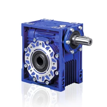
Is it Possible to Reverse the Direction of a Worm Gearbox?
Yes, it is possible to reverse the direction of a worm gearbox by changing the orientation of either the input or output shaft. However, reversing the direction of a worm gearbox can have some implications that need to be considered:
- Efficiency: Reversing the direction of a worm gearbox can potentially affect its efficiency. Worm gearboxes are typically more efficient in one direction of rotation due to the design of the worm and worm wheel.
- Backlash: Reversing the direction of rotation might lead to increased backlash or play in the gearbox, which can impact precision and smooth operation.
- Lubrication: Depending on the gearbox’s design, reversing the direction could affect lubrication distribution and lead to uneven wear on the gear teeth.
- Load: Reversing the direction might also impact the gearbox’s load-carrying capacity, especially if it’s designed for predominantly one-way operation.
- Noise and Vibration: Direction reversal can sometimes result in increased noise and vibration due to changes in gear engagement and meshing behavior.
If you need to reverse the direction of a worm gearbox, it’s advisable to consult the gearbox manufacturer’s guidelines and recommendations. They can provide insights into whether the specific gearbox model is suitable for reversible operation and any precautions or adjustments needed to ensure proper functioning.
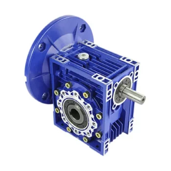
Energy Efficiency of a Worm Gearbox: What to Expect
The energy efficiency of a worm gearbox is an important factor to consider when evaluating its performance. Here’s what you can expect in terms of energy efficiency:
- Typical Efficiency Range: Worm gearboxes are known for their compact size and high gear reduction capabilities, but they can exhibit lower energy efficiency compared to other types of gearboxes. The efficiency of a worm gearbox typically falls in the range of 50% to 90%, depending on various factors such as design, manufacturing quality, lubrication, and load conditions.
- Inherent Losses: Worm gearboxes inherently involve sliding contact between the worm and worm wheel. This sliding contact generates friction, leading to energy losses in the form of heat. The sliding action also contributes to lower efficiency when compared to gearboxes with rolling contact.
- Helical-Worm Design: Some manufacturers offer helical-worm gearbox designs that combine elements of helical and worm gearing. These designs aim to improve efficiency by incorporating helical gears in the reduction stage, which can lead to higher efficiency compared to traditional worm gearboxes.
- Lubrication: Proper lubrication plays a significant role in minimizing friction and improving energy efficiency. Using high-quality lubricants and ensuring the gearbox is adequately lubricated can help reduce losses due to friction.
- Application Considerations: While worm gearboxes might have lower energy efficiency compared to other types of gearboxes, they still offer advantages in terms of compactness, high torque transmission, and simplicity. Therefore, the decision to use a worm gearbox should consider the specific requirements of the application, including the trade-off between energy efficiency and other performance factors.
When selecting a worm gearbox, it’s essential to consider the trade-offs between energy efficiency, torque transmission, gearbox size, and the specific needs of the application. Regular maintenance, proper lubrication, and selecting a well-designed gearbox can contribute to achieving the best possible energy efficiency within the limitations of worm gearbox technology.
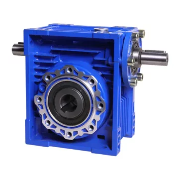
What is a Worm Gearbox and How Does It Work?
A worm gearbox, also known as a worm gear reducer, is a mechanical device used to transmit rotational motion and torque between non-parallel shafts. It consists of a worm screw and a worm wheel, both of which have helical teeth. The worm screw resembles a threaded cylinder, while the worm wheel is a gear with teeth that mesh with the worm screw.
The working principle of a worm gearbox involves the interaction between the worm screw and the worm wheel. When the worm screw is rotated, its helical teeth engage with the teeth of the worm wheel. As the worm screw rotates, it translates the rotational motion into a perpendicular motion, causing the worm wheel to rotate. This perpendicular motion allows the worm gearbox to achieve a high gear reduction ratio, making it suitable for applications that require significant speed reduction.
One of the key features of a worm gearbox is its ability to provide a high gear reduction ratio in a compact design. However, due to the sliding nature of the meshing teeth, worm gearboxes may exhibit higher friction and lower efficiency compared to other types of gearboxes. Therefore, they are often used in applications where efficiency is not the primary concern but where high torque and speed reduction are essential, such as conveyor systems, elevators, automotive steering systems, and certain industrial machinery.


editor by CX 2023-09-28
China wholesaler Wpx Worm Gear Reducer Vertical Reduction Gearbox Speed Servo-Worm Aluminium Drive Small Double Reduction Compact Worm Gear Boxes with high quality
Product Description
wpx worm gear reducer vertical reduction gearbox speed servo-worm Aluminium Drive Small Double Reduction gear box
Application of wpx worm gear reducer
A worm gear reducer is a type of mechanical transmission that uses a worm gear and a wheel gear to transmit power. The worm gear is a screw-shaped gear that meshes with the wheel gear, which is a spur gear. The worm gear drives the wheel gear, which results in a high reduction ratio.
A Wpx worm gear reducer is a specific type of worm gear reducer that is manufactured by the company Wpx. Wpx worm gear reducers are available in a variety of sizes and configurations, and they can be used in a variety of applications.
Some of the most common applications for Wpx worm gear reducers include:
- Lifts and elevators: Wpx worm gear reducers are used in the drive systems of lifts and elevators. The high torque of the Wpx worm gear reducer allows the lift or elevator to move smoothly and quietly.
- Conveyors: Wpx worm gear reducers are used in the drive systems of conveyors. The high torque of the Wpx worm gear reducer allows the conveyor to move heavy loads at a slow speed.
- Wind turbines: Wpx worm gear reducers are used in the drive systems of wind turbines. The high torque of the Wpx worm gear reducer allows the wind turbine to generate electricity even in low wind conditions.
- Machine tools: Wpx worm gear reducers are used in the drive systems of machine tools. The high torque of the Wpx worm gear reducer allows the machine tools to operate smoothly and precisely.
- Other applications: Wpx worm gear reducers are also used in a variety of other applications, such as:
- Robotics: Wpx worm gear reducers are used in the drive systems of robots. The high torque of the Wpx worm gear reducer allows the robots to move heavy loads with precision.
- Medical equipment: Wpx worm gear reducers are used in the drive systems of medical equipment, such as X-ray machines and MRI machines. The high torque of the Wpx worm gear reducer allows the equipment to operate smoothly and precisely.
Wpx worm gear reducers are a versatile and useful tool that can be used in a variety of applications. They are an efficient and effective way to transmit power in applications where high torque and low speed are required.
Here are some additional benefits of using Wpx worm gear reducers:
- High efficiency: Wpx worm gear reducers are very efficient, meaning that they can transmit a lot of power with minimal losses.
- Low noise: Wpx worm gear reducers are very quiet, making them ideal for use in applications where noise is a concern.
- Long life: Wpx worm gear reducers are very durable and can last for many years with proper maintenance.
If you are looking for a reducer that can provide high torque, low speed, efficiency, low noise, and long life, then a Wpx worm gear reducer is a good option to consider.
| Application: | Motor, Electric Cars, Motorcycle, Machinery, Marine, Toy, Agricultural Machinery, Car |
|---|---|
| Hardness: | Soft Tooth Surface |
| Installation: | 90 Degree |
| Layout: | Coaxial |
| Gear Shape: | Conical – Cylindrical Gear |
| Step: | Stepless |
| Samples: |
US$ 9999/Piece
1 Piece(Min.Order) | |
|---|
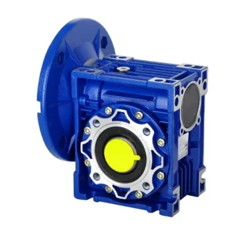
How to Install and Align a Worm Reducer Properly
Proper installation and alignment of a worm reducer are crucial for ensuring optimal performance and longevity. Follow these steps to install and align a worm reducer:
- Preparation: Gather all the necessary tools, equipment, and safety gear before starting the installation process.
- Positioning: Place the worm reducer in the desired location, ensuring that it is securely mounted to a stable surface. Use appropriate fasteners and mounting brackets as needed.
- Shaft Alignment: Check the alignment of the input and output shafts. Use precision measurement tools to ensure that the shafts are parallel and in line with each other.
- Base Plate Alignment: Align the base plate of the reducer with the foundation or mounting surface. Ensure that the base plate is level and properly aligned before securing it in place.
- Bolt Tightening: Gradually and evenly tighten the mounting bolts to the manufacturer’s specifications. This helps ensure proper contact between the reducer and the mounting surface.
- Check for Clearance: Verify that there is enough clearance for any rotating components or parts that may move during operation. Avoid any interference that could cause damage or performance issues.
- Lubrication: Apply the recommended lubricant to the worm reducer according to the manufacturer’s guidelines. Proper lubrication is essential for smooth operation and reducing friction.
- Alignment Testing: After installation, run the worm reducer briefly without a load to check for any unusual noises, vibrations, or misalignment issues.
- Load Testing: Gradually introduce the intended load to the worm reducer and monitor its performance. Ensure that the reducer operates smoothly and efficiently under the load conditions.
It’s important to refer to the manufacturer’s installation guidelines and specifications for your specific worm reducer model. Proper installation and alignment will contribute to the gearbox’s reliability, efficiency, and overall functionality.
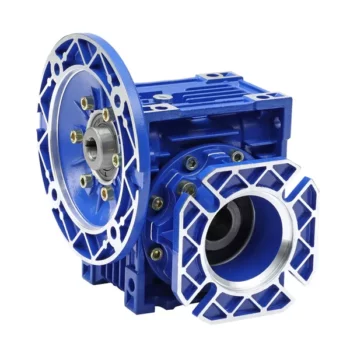
How to Calculate the Input and Output Speeds of a Worm Gearbox?
Calculating the input and output speeds of a worm gearbox involves understanding the gear ratio and the principles of gear reduction. Here’s how you can calculate these speeds:
- Input Speed: The input speed (N1) is the speed of the driving gear, which is the worm gear in this case. It is usually provided by the manufacturer or can be measured directly.
- Output Speed: The output speed (N2) is the speed of the driven gear, which is the worm wheel. To calculate the output speed, use the formula:
N2 = N1 / (Z1 * i)
Where:
N2 = Output speed (rpm)
N1 = Input speed (rpm)
Z1 = Number of teeth on the worm gear
i = Gear ratio (ratio of the number of teeth on the worm gear to the number of threads on the worm)
It’s important to note that worm gearboxes are designed for gear reduction, which means that the output speed is lower than the input speed. Additionally, the efficiency of the gearbox, friction, and other factors can affect the actual output speed. Calculating the input and output speeds is crucial for understanding the performance and capabilities of the worm gearbox in a specific application.
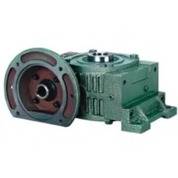
Can a Worm Gearbox Provide High Torque Output?
Yes, a worm gearbox is capable of providing high torque output due to its unique design and principle of operation. Worm gears are known for their high torque multiplication capabilities, making them suitable for applications that require significant torque transfer.
The torque output of a worm gearbox is influenced by several factors:
- Lead Angle: The lead angle of the worm affects the mechanical advantage of the gear system. A larger lead angle can result in higher torque output.
- Worm Diameter: A larger diameter worm can offer increased torque output as it provides more contact area with the gear.
- Gear Ratio: The gear ratio between the worm and the gear determines the torque multiplication factor. A higher gear ratio leads to higher torque output.
- Lubrication: Proper lubrication is essential to minimize friction and ensure efficient torque transmission.
- Material and Quality: High-quality materials and precision manufacturing contribute to the gearbox’s ability to handle high torque loads.
Due to their ability to provide high torque output in a compact form factor, worm gearboxes are commonly used in various industrial applications, including heavy machinery, construction equipment, conveyor systems, and more.


editor by CX 2023-09-13
China Low noise small engine reduction speed reducer stepper motor 90 degree RV030 RV040 RV050 RV063 worm gearbox double stage worm gearbox
Relevant Industries: Developing Substance Shops, Manufacturing Plant, Equipment Restore Retailers, Foods & Beverage Manufacturing unit, Farms, Printing Retailers, Building works , Power & Mining, Meals & Beverage Retailers, Other
Weight (KG): 2 KG
Personalized assist: OEM, ODM, OBM
Gearing Arrangement: Worm
Output Torque: 2.6-1760N.m
Enter Speed: 750~3500rpm
Output Pace: fourteen-280rpm
Merchandise title: Gray color worm reduction gearbox
Design: From RV25 up to RV185
Substance: Aluminum&iron cating
Color: K9149 (Gray )OR RAL5571(blue)
Ratio: 7.5,ten,15,20,30,forty,50,sixty,80,100
Guarantee: 1 yr after vessel date
Good quality Handle Method: ISO9001:2008
Port: ZheJiang or HangZhou Port,China
Goods Description
| Type | Worm Equipment Velocity Reducer/ gearbox |
| Model | WMRV twenty five/thirty/40/fifty/sixty three/seventy five/90/one hundred ten/130/150/185 |
| Ratio | 7.5,10,15,twenty,twenty five,30,40,fifty,sixty,eighty,100. |
| Color | Blue(RAL5571)/Silver grey (K9149) Or On Customer Request |
| Material | Aluminum alloy |
| Worm wheel: Aluminum Bronze or Zinc Bronze | |
| Worm shaft: 20CrMn Ti | |
| Output Shaft: metal-45# | |
| Packing | Carton, Honey Comb Carton, Wooden Scenario with picket pallet |
| Warranty | 1 12 months |
| Input Power | 0.09kw,.18kw,1.1KW,1.5KW,2.2KW,3KW,4KW,5.5KW,7.5KW,11Kw and so on. |
| Usages | Industrial Machine: Foodstuff Things, Ceramics, CHEMICAL, Packing, Dyeing,Wooden working, Glass. |
| IEC Flange | IEC normal flange or on customer request |
| Lubricant | Synthetic oil or worm gear oil |
Key Market Insights Related to Worm Reduction Gearboxes
A gearbox is a mechanical device that allows you to shift between different speeds or gears. It does so by using one or more clutches. Some gearboxes are single-clutch, while others use two clutches. You can even find a gearbox with closed bladders. These are also known as dual clutches and can shift gears more quickly than other types. Performance cars are designed with these types of gearboxes.
Backlash measurement
Gearbox backlash is a common component that can cause noise or other problems in a car. In fact, the beats and sets of gears in a gearbox are often excited by the oscillations of the engine torque. Noise from gearboxes can be significant, particularly in secondary shafts that engage output gears with a differential ring. To measure backlash and other dimensional variations, an operator can periodically take the output shaft’s motion and compare it to a known value.
A comparator measures the angular displacement between two gears and displays the results. In one method, a secondary shaft is disengaged from the gearbox and a control gauge is attached to its end. A threaded pin is used to secure the differential crown to the secondary shaft. The output pinion is engaged with the differential ring with the aid of a control gauge. The angular displacement of the secondary shaft is then measured by using the dimensions of the output pinion.
Backlash measurements are important to ensure the smooth rotation of meshed gears. There are various types of backlash, which are classified according to the type of gear used. The first type is called circumferential backlash, which is the length of the pitch circle around which the gear rotates to make contact. The second type, angular backlash, is defined as the maximum angle of movement between two meshed gears, which allows the other gear to move when the other gear is stationary.
The backlash measurement for gearbox is one of the most important tests in the manufacturing process. It is a criterion of tightness or looseness in a gear set, and too much backlash can jam a gear set, causing it to interface on the weaker part of its gear teeth. When backlash is too tight, it can lead to gears jamming under thermal expansion. On the other hand, too much backlash is bad for performance.
Worm reduction gearboxes
Worm reduction gearboxes are used in the production of many different kinds of machines, including steel and power plants. They are also used extensively in the sugar and paper industries. The company is constantly aiming to improve their products and services to remain competitive in the global marketplace. The following is a summary of key market insights related to this type of gearbox. This report will help you make informed business decisions. Read on to learn more about the advantages of this type of gearbox.
Compared to conventional gear sets, worm reduction gearboxes have few disadvantages. Worm gear reducers are commonly available and manufacturers have standardized their mounting dimensions. There are no unique requirements for shaft length, height, and diameter. This makes them a very versatile piece of equipment. You can choose to use one or combine several worm gear reducers to fit your specific application. And because they have standardized ratios, you will not have to worry about matching up multiple gears and determining which ones fit.
One of the primary disadvantages of worm reduction gearboxes is their reduced efficiency. Worm reduction gearboxes usually have a maximum reduction ratio of five to sixty. The higher-performance hypoid gears have an output speed of around ten to twelve revolutions. In these cases, the reduced ratios are lower than those with conventional gearing. Worm reduction gearboxes are generally more efficient than hypoid gear sets, but they still have a low efficiency.
The worm reduction gearboxes have many advantages over traditional gearboxes. They are simple to maintain and can work in a range of different applications. Because of their reduced speed, they are perfect for conveyor belt systems.
Worm reduction gearboxes with closed bladders
The worm and the gear mesh with each other in a combination of sliding and rolling movements. This sliding action is dominant at high reduction ratios, and the worm and gear are made of dissimilar metals, which results in friction and heat. This limits the efficiency of worm gears to around thirty to fifty percent. A softer material for the gear can be used to absorb shock loads during operation.
A normal gear changes its output independently once a sufficient load is applied. However, the backstop complicates the gear configuration. Worm gears require lubrication because of the sliding wear and friction introduced during movement. A common gear arrangement moves power at the peak load section of a tooth. The sliding happens at low speeds on either side of the apex and occurs at a low velocity.
Single-reduction gearboxes with closed bladders may not require a drain plug. The reservoir for a worm gear reducer is designed so that the gears are in constant contact with lubricant. However, the closed bladders will cause the worm gear to wear out more quickly, which can cause premature wear and increased energy consumption. In this case, the gears can be replaced.
Worm gears are commonly used for speed reduction applications. Unlike conventional gear sets, worm gears have higher reduction ratios. The number of gear teeth in the worm reduces the speed of a particular motor by a substantial amount. This makes worm gears an attractive option for hoisting applications. In addition to their increased efficiency, worm gears are compact and less prone to mechanical failure.
Shaft arrangement of a gearbox
The ray-diagram of a gearbox shows the arrangement of gears in the various shafts of the transmission. It also shows how the transmission produces different output speeds from a single speed. The ratios that represent the speed of the spindle are called the step ratio and the progression. A French engineer named Charles Renard introduced five basic series of gearbox speeds. The first series is the gear ratio and the second series is the reverse gear ratio.
The layout of the gear axle system in a gearbox relates to its speed ratio. In general, the speed ratio and the centre distance are coupled by the gear axles to form an efficient transmission. Other factors that may affect the layout of the gear axles include space constraints, the axial dimension, and the stressed equilibrium. In October 2009, the inventors of a manual transmission disclosed the invention as No. 2. These gears can be used to realize accurate gear ratios.
The input shaft 4 in the gear housing 16 is arranged radially with the gearbox output shaft. It drives the lubricating oil pump 2. The pump draws oil from a filter and container 21. It then delivers the lubricating oil into the rotation chamber 3. The chamber extends along the longitudinal direction of the gearbox input shaft 4, and it expands to its maximum diameter. The chamber is relatively large, due to a detent 43.
Different configurations of gearboxes are based on their mounting. The mounting of gearboxes to the driven equipment dictates the arrangement of shafts in the gearbox. In certain cases, space constraints also affect the shaft arrangement. This is the reason why the input shaft in a gearbox may be offset horizontally or vertically. However, the input shaft is hollow, so that it can be connected to lead through lines or clamping sets.
Mounting of a gearbox
In the mathematical model of a gearbox, the mounting is defined as the relationship between the input and output shafts. This is also known as the Rotational Mount. It is one of the most popular types of models used for drivetrain simulation. This model is a simplified form of the rotational mount, which can be used in a reduced drivetrain model with physical parameters. The parameters that define the rotational mount are the TaiOut and TaiIn of the input and output shaft. The Rotational Mount is used to model torques between these two shafts.
The proper mounting of a gearbox is crucial for the performance of the machine. If the gearbox is not aligned properly, it may result in excessive stress and wear. It may also result in malfunctioning of the associated device. Improper mounting also increases the chances of the gearbox overheating or failing to transfer torque. It is essential to ensure that you check the mounting tolerance of a gearbox before installing it in a vehicle.


editor by czh