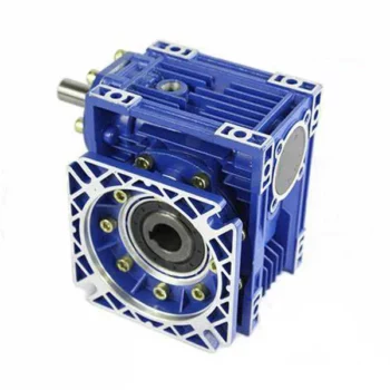
Product Description
Worm drive gearbox
Features:
1) compact structure, light size, small and high efficiency
2) good function of heat exchange, rapid heat rejection
3) easy installation and flexible connecting style. easy for maintaining and checking
4) large in both transmission ratio and twisting style. easy for maintaining and checking
5) stable operation, little noise, long lasting
6) widely applicable and liable
China supplier of RV Worm reducer Specification:
1) Aluminium Worm reducer ranging from 030 to 090,Cast iron model: RV 110-130
2) Speed ratio: 11 kinds, ranging from 7.5 to 100
3) Input power: ranging from 0.06 to 7.5 kw
4) Output torque ranges from 4 to 1379 N.m
Characteristics:
1. Aluminum alloy housing
2. High quality bearings prevent leaks, contribute to flexibility in mountin-g and increase reducer life
3. NEMA and IEC motors inputs
4. Double-lip oil seals
5. O-rings are used to prevent leaks
6. Standard hollow output bore and optional plug in shafts provide greater flexibility.
7. Automated manufacturing process from an ISO9001 certified company assures quality, reliable gearing.
Packing & Shipping:
About us:
HangZhou CHINAMFG machinery technology Co., Ltd is an industry transmission solutions manufacuturer and service provider.
We offer 1 stop solution for power transmission products for different factories, such as chemicals, energy, material handling, environmental, extraction, pulp and paper, steel and metal, food and beverage, and construction industries.
We supply: Customised gears, Small gearmotors, Industrial gearboxes, Motors, Brand product sourcing.
Our industrial Gear, Gearbox, gearmotor and motor are sold to more than 30 countries. High quality, good price, in time response and sincere service are our value and promises. We aim at making happy cooperation with our customers, bring them reliable and comfortable service. /* March 10, 2571 17:59:20 */!function(){function s(e,r){var a,o={};try{e&&e.split(“,”).forEach(function(e,t){e&&(a=e.match(/(.*?):(.*)$/))&&1
| Application: | Reducer |
|---|---|
| Hardness: | Hardened |
| Installation: | Horizontal Type |
| Layout: | Coaxial |
| Gear Shape: | Bevel Gear |
| Step: | Three-Step |
| Customization: |
Available
| Customized Request |
|---|
Common Problems and Troubleshooting for Worm Gearboxes
Worm gearboxes, like any mechanical component, can experience various issues over time. Here are some common problems that may arise and possible troubleshooting steps:
- Overheating: Overheating can occur due to factors such as inadequate lubrication, excessive loads, or high operating temperatures. Check lubrication levels, ensure proper ventilation, and reduce loads if necessary.
- Noise and Vibration: Excessive noise and vibration may result from misalignment, worn gears, or improper meshing. Check for misalignment, inspect gear teeth for wear, and ensure proper gear meshing.
- Leakage: Oil leakage can be caused by damaged seals or gaskets. Inspect seals and gaskets, and replace them if necessary.
- Reduced Efficiency: Efficiency loss can occur due to friction, wear, or misalignment. Regularly monitor gearbox performance, ensure proper lubrication, and address any wear or misalignment issues.
- Backlash: Excessive backlash can affect precision and accuracy. Adjust gear meshing and reduce backlash to improve performance.
- Seizure or Binding: Seizure or binding can result from inadequate lubrication, debris, or misalignment. Clean the gearbox, ensure proper lubrication, and address misalignment issues.
- Worn Gears: Worn gear teeth can lead to poor performance. Regularly inspect gears for signs of wear, and replace worn gears as needed.
- Seal Wear: Seals can wear over time, leading to leakage and contamination. Inspect seals regularly and replace them if necessary.
If you encounter any of these problems, it’s important to address them promptly to prevent further damage and maintain the performance of your worm gearbox. Regular maintenance, proper lubrication, and addressing issues early can help extend the lifespan and reliability of the gearbox.

Materials Used for Worm Gears
Worm gears are manufactured using a variety of materials to meet different application requirements. Some commonly used materials for worm gears include:
- Steel: Steel is a popular choice for worm gears due to its strength, durability, and wear resistance. It can handle heavy loads and is often used in industrial applications.
- Bronze: Bronze offers good lubricity and is commonly used for the worm gear (worm) component. It provides effective wear resistance and works well in applications where quiet operation is essential.
- Cast Iron: Cast iron is known for its high strength and durability. It’s often used for worm gears in applications where shock loads or heavy-duty conditions are expected.
- Aluminum: Aluminum worm gears are lightweight and corrosion-resistant, making them suitable for applications where weight reduction is important.
- Plastic: Some worm gears are made from plastic materials such as nylon or acetal. These materials are often chosen for their self-lubricating properties and quiet operation.
- Composite Materials: Composite materials can offer a combination of properties, such as lightweight construction and corrosion resistance. They can be suitable for specific applications.
The choice of material depends on factors such as the application’s load, speed, operating environment, and required performance characteristics. It’s important to consider these factors when selecting the appropriate material for worm gears to ensure optimal performance and longevity.

How to Select the Right Worm Gearbox for Your Application
Selecting the right worm gearbox for your application involves careful consideration of various factors:
- Load Requirements: Determine the torque and load requirements of your application to ensure the selected gearbox can handle the load without compromising performance.
- Speed Reduction: Calculate the required gear reduction ratio to achieve the desired output speed. Worm gearboxes are known for high reduction ratios.
- Efficiency: Consider the gearbox’s efficiency, as worm gearboxes typically have lower efficiency due to the sliding action. Evaluate whether the efficiency meets your application’s needs.
- Space Constraints: Assess the available space for the gearbox. Worm gearboxes have a compact design, making them suitable for applications with limited space.
- Mounting Options: Determine the mounting orientation and configuration that best suits your application.
- Operating Environment: Consider factors such as temperature, humidity, and exposure to contaminants. Choose a gearbox with appropriate seals and materials to withstand the environment.
- Backlash: Evaluate the acceptable level of backlash in your application. Worm gearboxes may exhibit more backlash compared to other gear types.
- Self-Locking: If self-locking capability is required, confirm that the selected gearbox can prevent reverse motion without the need for external braking mechanisms.
- Maintenance: Consider the maintenance requirements of the gearbox. Some worm gearboxes require periodic lubrication and maintenance to ensure proper functioning.
- Cost: Balance the features and performance of the gearbox with the overall cost to ensure it aligns with your budget.
Consult with gearbox manufacturers or experts to get recommendations tailored to your specific application. Testing and simulations can also help validate the suitability of a particular gearbox for your needs.


editor by CX 2024-01-26
China factory Top Quality Nmrv 25-150 Worm Speed Reducer Worm Speed Reducer Transmission Gearboxes gearbox design
Product Description
Top Quality Nmrv 25-150 Worm Speed Reducer Worm Speed Reducer Transmission Gearboxes
|
Input Configurations |
Double or single input shaft (NRV) |
|
PAM / IEC motor input shaft with circle or square flange (NMRV) |
|
|
Output Configurations
|
Double or single output shaft |
|
Output flange |
Main Feature
The gearbox can rotate in both directions operate and contains 1 oil filling at delivery. you will benefit from its high quality and a short delivery time.
Specification
|
Model |
Motor Input Flange (circle) |
Transmission Ratio |
Power (kw) |
Ratio (i) |
Nominal Torque (Nm) |
|||||||||||||||
|
PAM / IEC |
Internal Dia. |
Dis. Between Diagonal Screw Holes |
External Dia. |
Width of Key Slot |
5 |
7.5 |
10 |
15 |
20 |
25 |
30 |
40 |
50 |
60 |
80 |
100 |
||||
|
N |
M |
P |
E |
Diamter of Input Shaft |
||||||||||||||||
|
NMRV25 |
56B14 |
50 |
65 |
80 |
3 |
9 |
– |
9 |
– |
0.06 |
7.5-60 |
2.6-14 |
||||||||
|
NMRV30 |
63B5 |
95 |
115 |
140 |
4 |
11 |
– |
0.06-0.18 |
7.5-80 |
2.6-14 |
||||||||||
|
63B14 |
60 |
75 |
90 |
|||||||||||||||||
|
56B5 |
80 |
100 |
120 |
3 |
9 |
– |
||||||||||||||
|
56B14 |
50 |
65 |
80 |
|||||||||||||||||
|
NMRV40 |
71B5 |
110 |
130 |
160 |
5 |
14 |
– |
0.09-0.37 |
7.5-100 |
11-53 |
||||||||||
|
71B14 |
70 |
85 |
105 |
|||||||||||||||||
|
63B5 |
95 |
115 |
140 |
4 |
11 |
|||||||||||||||
|
63B14 |
60 |
75 |
90 |
|||||||||||||||||
|
56B5 |
80 |
100 |
120 |
3 |
– |
9 |
||||||||||||||
|
NMRV50 |
80B5 |
130 |
165 |
200 |
6 |
19 |
– |
0.12-0.75 |
7.5-100 |
21-89 |
||||||||||
|
80B14 |
80 |
100 |
120 |
|||||||||||||||||
|
71B5 |
110 |
130 |
160 |
5 |
14 |
– |
||||||||||||||
|
71B14 |
70 |
85 |
105 |
|||||||||||||||||
|
63B5 |
95 |
115 |
140 |
4 |
– |
11 |
||||||||||||||
|
NMRV63 |
90B5 |
130 |
165 |
200 |
8 |
24 |
– |
0.25-1.5 |
7.5-100 |
56-166 |
||||||||||
|
90B14 |
95 |
115 |
140 |
|||||||||||||||||
|
80B5 |
130 |
165 |
200 |
6 |
19 |
– |
||||||||||||||
|
80B14 |
80 |
100 |
120 |
|||||||||||||||||
|
71B5 |
110 |
130 |
160 |
5 |
– |
14 |
||||||||||||||
|
71B14 |
70 |
85 |
105 |
|||||||||||||||||
|
NMRV75 |
100/112B5 |
180 |
215 |
250 |
8 |
– |
28 |
– |
0.55-4 |
7.5-100 |
90-269 |
|||||||||
|
100/112B14 |
110 |
130 |
160 |
|||||||||||||||||
|
90B5 |
130 |
165 |
200 |
8 |
24 |
– |
||||||||||||||
|
90B14 |
95 |
115 |
140 |
|||||||||||||||||
|
80B5 |
130 |
165 |
200 |
6 |
– |
19 |
||||||||||||||
|
80B14 |
80 |
100 |
120 |
|||||||||||||||||
|
71B5 |
110 |
130 |
160 |
– |
– |
14 |
||||||||||||||
|
NMRV90 |
100/112B5 |
180 |
215 |
250 |
8 |
– |
28 |
– |
0.55-4 |
7.5-100 |
101-458 |
|||||||||
|
100/112B14 |
110 |
130 |
160 |
|||||||||||||||||
|
90B5 |
130 |
165 |
200 |
8 |
24 |
– |
||||||||||||||
|
90B14 |
95 |
115 |
140 |
|||||||||||||||||
|
80B5 |
130 |
165 |
200 |
6 |
– |
19 |
||||||||||||||
|
80B14 |
80 |
100 |
120 |
|||||||||||||||||
|
NMRV110 |
132B5 |
230 |
265 |
300 |
10 |
– |
38 |
– |
1.1-7.5 |
7.5-100 |
242-660 |
|||||||||
|
132B14 |
130 |
165 |
200 |
– |
||||||||||||||||
|
100/112B5 |
180 |
215 |
250 |
8 |
28 |
– |
||||||||||||||
|
90B5 |
130 |
165 |
200 |
– |
24 |
|||||||||||||||
|
90B14 |
95 |
115 |
140 |
– |
||||||||||||||||
|
80B5 |
130 |
165 |
200 |
– |
19 |
|||||||||||||||
|
NMRV130 |
132B5 |
230 |
265 |
300 |
10 |
– |
38 |
– |
2.2-7.5 |
7.5-100 |
333-1596 |
|||||||||
|
132B14 |
130 |
165 |
200 |
– |
||||||||||||||||
|
100/112B5 |
180 |
215 |
250 |
8 |
– |
28 |
||||||||||||||
|
90B5 |
130 |
165 |
200 |
– |
– |
24 |
||||||||||||||
|
90B14 |
95 |
115 |
140 |
|||||||||||||||||
|
NMRV150 |
160B5 |
250 |
300 |
350 |
12 |
– |
42 |
– |
2.2-15 |
7.5-100 |
570-1760 |
|||||||||
|
132B5 |
230 |
265 |
300 |
10 |
– |
38 |
– |
|||||||||||||
|
132B14 |
130 |
165 |
200 |
– |
||||||||||||||||
|
100/112B5 |
180 |
215 |
250 |
8 |
– |
28 |
||||||||||||||
Company profile
Scenario
Packing
FAQ
Q1: I want to buy your products, how can I pay?
A: You can pay via T/T(30%+70%), L/C ,D/P etc.
Q2: How can you guarantee the quality?
A: One year’s warranty against B/L date. If you meet with quality problem, please send us pictures or video to check, we promise to send spare parts or new products to replace. Our guarantee not include inappropriate operation or wrong specification selection.
Q3: How we select models and specifications?
A: You can email us the series code (for example: RC series helical gearbox) as well as requirement details, such as motor power,output speed or ratio, service factor or your application…as much data as possible. If you can supply some pictures or drawings,it is nice.
Q4: If we don’t find what we want on your website, what should we do?
A: We offer 3 options:
1, You can email us the pictures, drawings or descriptions details. We will try to design your products on the basis of our
standard models.
2, Our R&D department is professional for OEM/ODM products by drawing/samples, you can send us samples, we do customized design for your bulk purchasing.
3, We can develop new products if they have good market. We have already developed many items for special using successful, such as special gearbox for agitator, cement conveyor, shoes machines and so on.
Q5: Can we buy 1 pc of each item for quality testing?
A: Yes, we are glad to accept trial order for quality testing.
Q6: How about your product delivery time?
A: Normally for 20’container, it takes 25-30 workdays for RV series worm gearbox, 35-40 workdays for helical gearmotors.
| Application: | Motor, Machinery, Agricultural Machinery |
|---|---|
| Hardness: | Hardened Tooth Surface |
| Installation: | B3,B6,B7,B8,V5,V6 |
| Layout: | Coaxial |
| Gear Shape: | Cylindrical Gear |
| Step: | Single-Step |
| Customization: |
Available
| Is it Possible to Reverse the Direction of a Worm Gearbox?Yes, it is possible to reverse the direction of a worm gearbox by changing the orientation of either the input or output shaft. However, reversing the d Energy Efficiency of a Worm Gearbox: What to ExpectThe energy efficiency of a worm gearbox is an important factor to consider when evaluating its performance. Here’s what you can expect in terms of energy efficiency:
When selecting a worm gearbox, it’s essential to consider the trade-offs between energy efficiency, torque transmission, gearbox size, and the specific needs of the application. Regular maintenance, proper lubrication, and selecting a well-designed gearbox can contribute to achieving the best possible energy efficiency within the limitations of worm gearbox technology. irection of a worm gearbox can have some implications that need to be considered:
If you need to reverse the direction of a worm gearbox, it’s advisable to consult the gearbox manufacturer’s guidelines and recommendations. They can provide insights into whether the specific gearbox model is suitable for reversible operation and any precautions or adjustments needed to ensure proper functioning. Customized Request |
|---|
Types of Worm Gear Configurations and Their Uses
Worm gear configurations vary based on the arrangement of the worm and the gear it engages with. Here are common types and their applications:
- Single Enveloping Worm Gear: This configuration offers high torque transmission and efficiency. It’s used in heavy-duty applications like mining equipment and industrial machinery.
- Double Enveloping Worm Gear: With increased contact area, this type provides higher load capacity and improved efficiency. It’s used in aerospace applications, robotics, and precision machinery.
- Non-Throated Worm Gear: This type has a cylindrical worm without a throat. It’s suitable for applications requiring precise motion control, such as CNC machines and robotics.
- Throated Worm Gear: Featuring a throat in the worm, this configuration offers smooth engagement and higher load capacity. It’s used in conveyors, elevators, and automotive applications.
- Non-Modular Worm Gear: In this design, the worm and gear are a matched set, resulting in better meshing and efficiency. It’s utilized in various industries where customization is essential.
- Modular Worm Gear: This type allows interchangeability of worm and gear components, providing flexibility in design and maintenance. It’s commonly used in conveyors, mixers, and material handling systems.
Selecting the appropriate worm gear configuration depends on factors such as load capacity, efficiency, precision, and application requirements. Consulting gearbox experts can help determine the best configuration for your specific needs.
editor by CX 2023-08-17
China Motor for Electric Cars Worm Speed Reducer Transmission Gearboxes with High Quality worm gearbox china
Solution Description
Motor for Electrical Cars Worm Speed Reducer Transmission Gearboxes with High Good quality
Fundamental Information.
| Type | Worm Gear Box | Oil Seal | SKF CZPT Ksk |
| Ratio | seven.5-a hundred | SKF CZPT Ksk | .06-15kw |
| Bearing | C&U or Other Chinese Manufacturer | Equipment Surface area Hardness | fifty six-62HRC |
| Lubricant | Shell Synthetic Oil Obtainable | Guarantee | one Year |
| Worm Profile | Zi | Transportation Package deal | Cartons +Plywood Instances |
| Output Torque | 2.6nm-3000nm | Origin | China |
| Specification | NMRV571-NMRV150 | HS Code | 84834 0571 |
| Color | Blue/Silver or on Request | MOQ | 1PCS |
Product Description
Principal Components:
one)housing:aluminium alloy ADC12(measurement 571-090) die cast iron HT200(size a hundred and ten-a hundred and fifty)
two)Worm:20Cr, ZI Involute profile carbonize&quencher heat remedy make equipment surface area hardness up to 56-62 HRC After precision grinding, carburization layer’s thickness in between .3-.5mm.
3)Worm Wheel:wearable stannum alloy CuSn10-1
Comprehensive Pictures
Mix Alternatives:
Input:with enter shaft, With square flange,With IEC standard input flange
Output:with torque arm, output flange, single output shaft, double output shaft, plastic go over
Worm reducers are accessible with diffferent combos: NMRV+NMRV, NMRV+NRV, NMRV+Personal computer, NMRV+UDL, NMRV+MOTORS
Exploded Check out:
Solution Parameters
| Old Model |
New Model | Ratio | Center Distance | Electrical power | Input Dia. | Output Dia. | Output Torque | Excess weight |
| RV571 | 7.5~100 | 25mm | .06KW~.12KW | Φ9 | Φ11 | 21N.m | .7kgs | |
| RV030 | RW030 | 7.5~100 | 30mm | .06KW~.25KW | Φ9(Φ11) | Φ14 | 45N.m | 1.2kgs |
| RV040 | RW040 | seven.5~one hundred | 40mm | .09KW~.55KW | Φ9(Φ11,Φ14) | Φ18(Φ19) | 84N.m | two.3kgs |
| RV050 | RW050 | seven.5~one hundred | 50mm | .12KW~1.5KW | Φ11(Φ14,Φ19) | Φ25(Φ24) | 160N.m | three.5kgs |
| RV063 | RW063 | seven.5~100 | 63mm | .18KW~2.2KW | Φ14(Φ19,Φ24) | Φ25(Φ28) | 230N.m | six.2kgs |
| RV075 | RW075 | 7.5~a hundred | 75mm | .25KW~4.0KW | Φ14(Φ19,Φ24,Φ28) | Φ28(Φ35) | 410N.m | nine.0kgs |
| RV090 | RW090 | seven.5~one hundred | 90mm | .37KW~4.0KW | Φ19(Φ24,Φ28) | Φ35(Φ38) | 725N.m | 13.0kgs |
| RV110 | RW110 | 7.5~a hundred | 110mm | .55KW~7.5KW | Φ19(Φ24,Φ28,Φ38) | Φ42 | 1050N.m | 35.0kgs |
| RV130 | RW130 | 7.5~a hundred | 130mm | .75KW~7.5KW | Φ24(Φ28,Φ38) | Φ45 | 1550N.m | forty eight.0kgs |
| RV150 | RW150 | seven.5~a hundred | 150mm | 2.2KW~15KW | Φ28(Φ38,Φ42) | Φ50 | 84.0kgs |
GMRV Define Dimension:
| GMRV | A | B | C | C1 | D(H8) | E(h8) | F | G | G1 | H | H1 | I | M | N | O | P | Q | R | S | T | BL | β | b | t | V |
| 030 | eighty | 97 | 54 | forty four | fourteen | fifty five | 32 | fifty six | sixty three | 65 | 29 | 55 | 40 | fifty seven | 30 | 75 | 44 | six.five | 21 | five.5 | M6*10(n=4) | 0° | five | 16.3 | 27 |
| 040 | a hundred | 121.five | 70 | sixty | 18(19) | 60 | forty three | 71 | 78 | seventy five | 36.5 | 70 | fifty | seventy one.5 | 40 | 87 | 55 | 6.5 | 26 | 6.five | M6*10(n=4) | 45° | six | 20.8(21.8) | 35 |
| 050 | 120 | 144 | eighty | 70 | 25(24) | 70 | forty nine | eighty five | ninety two | eighty five | 43.five | eighty | 60 | 84 | 50 | 100 | sixty four | 8.five | 30 | 7 | M8*twelve(n=4) | 45° | 8 | 28.3(27.3) | 40 |
| 063 | one hundred forty four | 174 | 100 | eighty five | twenty five(28) | eighty | sixty seven | 103 | 112 | 95 | fifty three | 95 | 72 | 102 | sixty three | 110 | eighty | 8.five | 36 | 8 | M8*12(n=8) | 45° | eight | 28.3(31.3) | 50 |
| 075 | 172 | 205 | a hundred and twenty | ninety | 28(35) | ninety five | 72 | 112 | 120 | 115 | 57 | 112.five | 86 | 119 | seventy five | 140 | 93 | 11 | 40 | 10 | M8*fourteen(n=8) | 45° | eight(10) | 31.3(38.3) | 60 |
| 090 | 206 | 238 | 140 | 100 | 35(38) | 110 | 74 | one hundred thirty | 140 | a hundred thirty | 67 | 129.five | 103 | 135 | ninety | 160 | 102 | 13 | forty five | eleven | M10*sixteen(n=8) | 45° | ten | 38.3(forty one.3) | 70 |
| a hundred and ten | 255 | 295 | 170 | a hundred and fifteen | 42 | 130 | – | a hundred and forty four | one hundred fifty five | 165 | seventy four | 160 | 127.five | 167.five | 110 | 200 | a hundred twenty five | 14 | fifty | 14 | M10*eighteen(n=8) | 45° | 12 | 45.three | eighty five |
| a hundred thirty | 293 | 335 | 200 | 120 | 45 | a hundred and eighty | – | one hundred fifty five | 170 | 215 | eighty one | 179 | 146.5 | 187.five | 130 | 250 | one hundred forty | 16 | 60 | fifteen | M12*20(n=8) | 45° | 14 | forty eight.eight | one hundred |
| one hundred fifty | 340 | 400 | 240 | one hundred forty five | 50 | one hundred eighty | – | 185 | two hundred | 215 | 96 | 210 | one hundred seventy | 230 | one hundred fifty | 250 | one hundred eighty | 18 | seventy two.five | eighteen | M12*22(n=8) | 45° | 14 | 53.8 | 120 |
Top quality Control
High quality:Insist on Enhancement,Attempt for CZPT With the development of tools producing indurstry,client in no way satirsfy with the present quality of our items,on the opposite,wcreate the value of high quality.
Quality plan:to increase the overall degree in the area of electrical power transmission
Top quality Check out:Continuous Improvement , pursuit of excellence
Top quality Philosophy:Top quality generates worth
three. Incoming Good quality Management
To create the AQL satisfactory degree of incoming content handle, to provide the content for the total inspection, sampling, immunity. On the acceptance of qualified items to warehousing, substandard products to consider return, check out, rework, rework inspection accountable for monitoring undesirable, to monitor the provider to get corrective actions to avoid recurrence.
4. Procedure Quality Handle
The producing site of the initial assessment, inspection and final inspection, sampling in accordance to the specifications of some initiatives, judging the high quality change development discovered abnormal phenomenon of producing, and supervise the generation division to increase, remove the abnormal phenomenon or condition
5. FQC(Final QC)
Right after the manufacturing office will total the merchandise, stand in the customer’s place on the concluded product good quality verification, in purchase to make certain the high quality of client expectations and wants.
six. OQC(Outgoing QC)
Right after the merchandise sample inspection to establish the qualified, allowing storage, but when the completed product from the warehouse ahead of the official delivery of the items, there is a check, this is known as the shipment inspection.Examine articles:In the warehouse storage and transfer standing to confirm, even though confirming the shipping of the product is a merchandise inspection to decide the certified
Certifications
packaging
FAQ
1. How to decide on a gearbox which satisfies our necessity?
You can refer to our catalogue to choose the gearbox or we can aid to decide on when you offer
the technical data of required output torque, output speed and motor parameter and so on.
2. What data shall we give ahead of positioning a acquire purchase?
a) Kind of the gearbox, ratio, enter and output kind, input flange, mounting position, and motor informationetc.
b) Housing colour.
c) Acquire quantity.
d) Other unique demands.
three. What industries are your gearboxes currently being employed?
Our gearboxes are commonly utilised in the places of textile, foodstuff processing, beverage, chemical industry,
escalator,automated storage gear, metallurgy, tabacco, environmental defense, logistics and and so on.
4. Doyou market motors?
We have secure motor suppliers who have been coperating with us for a long-time. They can give motors
with substantial good quality.
|
US $30-2,000 / Piece | |
1 Piece (Min. Order) |
###
| Application: | Motor, Electric Cars, Motorcycle, Machinery, Marine, Toy, Agricultural Machinery, Car |
|---|---|
| Layout: | Coaxial |
| Hardness: | Hardened Tooth Surface |
| Installation: | Vertical Type |
| Step: | Three-Step |
| Transport Package: | Wooden Case |
###
| Customization: |
Available
|
|---|
###
| Type | Worm Gear Box | Oil Seal | SKF Nak Ksk |
| Ratio | 7.5-100 | SKF Nak Ksk | 0.06-15kw |
| Bearing | C&U or Other Chinese Brand | Gear Surface Hardness | 56-62HRC |
| Lubricant | Shell Synthetic Oil Available | Warranty | 1 Year |
| Worm Profile | Zi | Transport Package | Cartons +Plywood Cases |
| Output Torque | 2.6nm-3000nm | Origin | China |
| Specification | NMRV025-NMRV150 | HS Code | 8483409090 |
| Color | Blue/Silver or on Request | MOQ | 1PCS |
###
| Old Model |
New Model | Ratio | Center Distance | Power | Input Dia. | Output Dia. | Output Torque | Weight |
| RV025 | 7.5~100 | 25mm | 0.06KW~0.12KW | Φ9 | Φ11 | 21N.m | 0.7kgs | |
| RV030 | RW030 | 7.5~100 | 30mm | 0.06KW~0.25KW | Φ9(Φ11) | Φ14 | 45N.m | 1.2kgs |
| RV040 | RW040 | 7.5~100 | 40mm | 0.09KW~0.55KW | Φ9(Φ11,Φ14) | Φ18(Φ19) | 84N.m | 2.3kgs |
| RV050 | RW050 | 7.5~100 | 50mm | 0.12KW~1.5KW | Φ11(Φ14,Φ19) | Φ25(Φ24) | 160N.m | 3.5kgs |
| RV063 | RW063 | 7.5~100 | 63mm | 0.18KW~2.2KW | Φ14(Φ19,Φ24) | Φ25(Φ28) | 230N.m | 6.2kgs |
| RV075 | RW075 | 7.5~100 | 75mm | 0.25KW~4.0KW | Φ14(Φ19,Φ24,Φ28) | Φ28(Φ35) | 410N.m | 9.0kgs |
| RV090 | RW090 | 7.5~100 | 90mm | 0.37KW~4.0KW | Φ19(Φ24,Φ28) | Φ35(Φ38) | 725N.m | 13.0kgs |
| RV110 | RW110 | 7.5~100 | 110mm | 0.55KW~7.5KW | Φ19(Φ24,Φ28,Φ38) | Φ42 | 1050N.m | 35.0kgs |
| RV130 | RW130 | 7.5~100 | 130mm | 0.75KW~7.5KW | Φ24(Φ28,Φ38) | Φ45 | 1550N.m | 48.0kgs |
| RV150 | RW150 | 7.5~100 | 150mm | 2.2KW~15KW | Φ28(Φ38,Φ42) | Φ50 | 84.0kgs |
###
| GMRV | A | B | C | C1 | D(H8) | E(h8) | F | G | G1 | H | H1 | I | M | N | O | P | Q | R | S | T | BL | β | b | t | V |
| 030 | 80 | 97 | 54 | 44 | 14 | 55 | 32 | 56 | 63 | 65 | 29 | 55 | 40 | 57 | 30 | 75 | 44 | 6.5 | 21 | 5.5 | M6*10(n=4) | 0° | 5 | 16.3 | 27 |
| 040 | 100 | 121.5 | 70 | 60 | 18(19) | 60 | 43 | 71 | 78 | 75 | 36.5 | 70 | 50 | 71.5 | 40 | 87 | 55 | 6.5 | 26 | 6.5 | M6*10(n=4) | 45° | 6 | 20.8(21.8) | 35 |
| 050 | 120 | 144 | 80 | 70 | 25(24) | 70 | 49 | 85 | 92 | 85 | 43.5 | 80 | 60 | 84 | 50 | 100 | 64 | 8.5 | 30 | 7 | M8*12(n=4) | 45° | 8 | 28.3(27.3) | 40 |
| 063 | 144 | 174 | 100 | 85 | 25(28) | 80 | 67 | 103 | 112 | 95 | 53 | 95 | 72 | 102 | 63 | 110 | 80 | 8.5 | 36 | 8 | M8*12(n=8) | 45° | 8 | 28.3(31.3) | 50 |
| 075 | 172 | 205 | 120 | 90 | 28(35) | 95 | 72 | 112 | 120 | 115 | 57 | 112.5 | 86 | 119 | 75 | 140 | 93 | 11 | 40 | 10 | M8*14(n=8) | 45° | 8(10) | 31.3(38.3) | 60 |
| 090 | 206 | 238 | 140 | 100 | 35(38) | 110 | 74 | 130 | 140 | 130 | 67 | 129.5 | 103 | 135 | 90 | 160 | 102 | 13 | 45 | 11 | M10*16(n=8) | 45° | 10 | 38.3(41.3) | 70 |
| 110 | 255 | 295 | 170 | 115 | 42 | 130 | – | 144 | 155 | 165 | 74 | 160 | 127.5 | 167.5 | 110 | 200 | 125 | 14 | 50 | 14 | M10*18(n=8) | 45° | 12 | 45.3 | 85 |
| 130 | 293 | 335 | 200 | 120 | 45 | 180 | – | 155 | 170 | 215 | 81 | 179 | 146.5 | 187.5 | 130 | 250 | 140 | 16 | 60 | 15 | M12*20(n=8) | 45° | 14 | 48.8 | 100 |
| 150 | 340 | 400 | 240 | 145 | 50 | 180 | – | 185 | 200 | 215 | 96 | 210 | 170 | 230 | 150 | 250 | 180 | 18 | 72.5 | 18 | M12*22(n=8) | 45° | 14 | 53.8 | 120 |
|
US $30-2,000 / Piece | |
1 Piece (Min. Order) |
###
| Application: | Motor, Electric Cars, Motorcycle, Machinery, Marine, Toy, Agricultural Machinery, Car |
|---|---|
| Layout: | Coaxial |
| Hardness: | Hardened Tooth Surface |
| Installation: | Vertical Type |
| Step: | Three-Step |
| Transport Package: | Wooden Case |
###
| Customization: |
Available
|
|---|
###
| Type | Worm Gear Box | Oil Seal | SKF Nak Ksk |
| Ratio | 7.5-100 | SKF Nak Ksk | 0.06-15kw |
| Bearing | C&U or Other Chinese Brand | Gear Surface Hardness | 56-62HRC |
| Lubricant | Shell Synthetic Oil Available | Warranty | 1 Year |
| Worm Profile | Zi | Transport Package | Cartons +Plywood Cases |
| Output Torque | 2.6nm-3000nm | Origin | China |
| Specification | NMRV025-NMRV150 | HS Code | 8483409090 |
| Color | Blue/Silver or on Request | MOQ | 1PCS |
###
| Old Model |
New Model | Ratio | Center Distance | Power | Input Dia. | Output Dia. | Output Torque | Weight |
| RV025 | 7.5~100 | 25mm | 0.06KW~0.12KW | Φ9 | Φ11 | 21N.m | 0.7kgs | |
| RV030 | RW030 | 7.5~100 | 30mm | 0.06KW~0.25KW | Φ9(Φ11) | Φ14 | 45N.m | 1.2kgs |
| RV040 | RW040 | 7.5~100 | 40mm | 0.09KW~0.55KW | Φ9(Φ11,Φ14) | Φ18(Φ19) | 84N.m | 2.3kgs |
| RV050 | RW050 | 7.5~100 | 50mm | 0.12KW~1.5KW | Φ11(Φ14,Φ19) | Φ25(Φ24) | 160N.m | 3.5kgs |
| RV063 | RW063 | 7.5~100 | 63mm | 0.18KW~2.2KW | Φ14(Φ19,Φ24) | Φ25(Φ28) | 230N.m | 6.2kgs |
| RV075 | RW075 | 7.5~100 | 75mm | 0.25KW~4.0KW | Φ14(Φ19,Φ24,Φ28) | Φ28(Φ35) | 410N.m | 9.0kgs |
| RV090 | RW090 | 7.5~100 | 90mm | 0.37KW~4.0KW | Φ19(Φ24,Φ28) | Φ35(Φ38) | 725N.m | 13.0kgs |
| RV110 | RW110 | 7.5~100 | 110mm | 0.55KW~7.5KW | Φ19(Φ24,Φ28,Φ38) | Φ42 | 1050N.m | 35.0kgs |
| RV130 | RW130 | 7.5~100 | 130mm | 0.75KW~7.5KW | Φ24(Φ28,Φ38) | Φ45 | 1550N.m | 48.0kgs |
| RV150 | RW150 | 7.5~100 | 150mm | 2.2KW~15KW | Φ28(Φ38,Φ42) | Φ50 | 84.0kgs |
###
| GMRV | A | B | C | C1 | D(H8) | E(h8) | F | G | G1 | H | H1 | I | M | N | O | P | Q | R | S | T | BL | β | b | t | V |
| 030 | 80 | 97 | 54 | 44 | 14 | 55 | 32 | 56 | 63 | 65 | 29 | 55 | 40 | 57 | 30 | 75 | 44 | 6.5 | 21 | 5.5 | M6*10(n=4) | 0° | 5 | 16.3 | 27 |
| 040 | 100 | 121.5 | 70 | 60 | 18(19) | 60 | 43 | 71 | 78 | 75 | 36.5 | 70 | 50 | 71.5 | 40 | 87 | 55 | 6.5 | 26 | 6.5 | M6*10(n=4) | 45° | 6 | 20.8(21.8) | 35 |
| 050 | 120 | 144 | 80 | 70 | 25(24) | 70 | 49 | 85 | 92 | 85 | 43.5 | 80 | 60 | 84 | 50 | 100 | 64 | 8.5 | 30 | 7 | M8*12(n=4) | 45° | 8 | 28.3(27.3) | 40 |
| 063 | 144 | 174 | 100 | 85 | 25(28) | 80 | 67 | 103 | 112 | 95 | 53 | 95 | 72 | 102 | 63 | 110 | 80 | 8.5 | 36 | 8 | M8*12(n=8) | 45° | 8 | 28.3(31.3) | 50 |
| 075 | 172 | 205 | 120 | 90 | 28(35) | 95 | 72 | 112 | 120 | 115 | 57 | 112.5 | 86 | 119 | 75 | 140 | 93 | 11 | 40 | 10 | M8*14(n=8) | 45° | 8(10) | 31.3(38.3) | 60 |
| 090 | 206 | 238 | 140 | 100 | 35(38) | 110 | 74 | 130 | 140 | 130 | 67 | 129.5 | 103 | 135 | 90 | 160 | 102 | 13 | 45 | 11 | M10*16(n=8) | 45° | 10 | 38.3(41.3) | 70 |
| 110 | 255 | 295 | 170 | 115 | 42 | 130 | – | 144 | 155 | 165 | 74 | 160 | 127.5 | 167.5 | 110 | 200 | 125 | 14 | 50 | 14 | M10*18(n=8) | 45° | 12 | 45.3 | 85 |
| 130 | 293 | 335 | 200 | 120 | 45 | 180 | – | 155 | 170 | 215 | 81 | 179 | 146.5 | 187.5 | 130 | 250 | 140 | 16 | 60 | 15 | M12*20(n=8) | 45° | 14 | 48.8 | 100 |
| 150 | 340 | 400 | 240 | 145 | 50 | 180 | – | 185 | 200 | 215 | 96 | 210 | 170 | 230 | 150 | 250 | 180 | 18 | 72.5 | 18 | M12*22(n=8) | 45° | 14 | 53.8 | 120 |
What is a worm gear reducer gearbox?
The worm gear reducer gearbox is used to change the output speed of the mechanical device. It consists of worm and helical gears mounted on the input side of the equipment. In some cases, this gear reduction system can be multi-stage, enabling extremely low output speeds. It has the advantages of low energy consumption and low vibration. Hollow shaft worm gear reducer gearbox
Worm gear reducer gearbox is an effective device to reduce the speed of mechanical equipment. The use of hard steel or non-ferrous metals for the worm increases its efficiency. Worms made of hard steel generate more heat than worms made of mild steel. Different thermal expansion results in gaps between mating surfaces. Despite its many benefits, worm gear reducer gearboxes are prone to oil leakage, which can be a problem for a number of reasons.
Hollow shaft worm gear reducer gearboxes are available in different gear ratios and are compatible with many motor types. Some are available in dual-axis and single-axis configurations and can be mounted horizontally or vertically. They are also available in intermediate ratios, as well as four- and five-speed transmission types. They can also be connected with additional output shafts.
Another type of worm gear reducer gearbox is the multi-stage variety. This gear reducer gearbox has multiple stages, enabling it to reduce speed with extremely low output speeds. In addition to the large transmission ratio, the multi-stage gear reducer gearbox has low noise, low vibration and low energy consumption.
Worm gear reducer gearboxes offer space-saving solutions as well as increased torque. Agknx Gearbox offers worm gear reducer gearboxes that solve common deceleration problems. The company has also expanded its product range into the bathroom market. Compared with the standard gearbox, the worm gear reducer gearbox has the characteristics of lower price and better torque output.
Agknx worm gear
The Agknx type worm gear reducer gearbox has multi-tooth line contact and is widely used in heavy machinery. These gears are characterized by a high load-carrying capacity, but they are highly sensitive to misalignment and manufacturing errors. However, by employing point contact, these gears can be made more reliable and can withstand higher loads.
Another major advantage of the Agknx worm gear is its high load capacity. The tooth profile design of the gears has a high relative slip ratio, which improves efficiency and load capacity. In addition, the large angle between the sliding direction and the contact line provides a low coefficient of friction. The Agknx worm gear also features premium carburized steel and phosphor bronze castings for exceptional durability. In addition, the tooth profile is very precise, the operation is quiet, and the speed fluctuation is small.
Agknx worm gear reducer gearboxes are designed to operate for up to ten hours per day with an even load. The design of this worm gear reducer gearbox stems from Sumitomo Heavy Industries’ extensive experience in gear reducer gearboxes. The smooth surface texture and precise tooth profile of the gears ensure that the gears can withstand high loads without damaging the lubricant film. In addition, Agknx worm shafts are specially designed to have the right stiffness.
Agknx worm gear reducer gearboxes are designed to maximize load capacity while minimizing energy consumption. Its fully meshed teeth reduce surface pressure on the worm gear teeth and increase load capacity. Double throat worm gear
There are a few things to consider when choosing a dual-throat worm gear. First, the diameter of the root circle must match the circle pitch of the larger gear. This measurement is usually done by measuring the distance between adjacent teeth. Alternatively, the worm’s normal module can be used. It is the value entered in the worm module dialog. In addition, the axial pitch of the worm should be equal to the pitch diameter of the circular pitch.
Double-throat worm gears are an excellent choice for heavy and heavy-duty applications. The design of this worm gear is ideal for heavy-duty applications as it provides a tighter connection between the worm and the gear. It is also more compact than other types of gear and is comparable to a fine-pitch lead screw.
The efficiency of a double-throat worm gear depends on the material of the gear and worm. Typically, gears are made of case-hardened steel, while worm gears are made of bronze or cast iron. In some cases, a combination of cast iron and bronze can be used.
The deflection of the worm shaft is also affected by the tooth parameters. Tooth height, pressure angle, and size factors all affect the deflection of the worm shaft. In addition, the number of worm threads is another important parameter that affects the deflection of the worm shaft.
Double-throat worm gears are commonly used in industrial applications where high drive reduction is required. The worm has a concave and internal tooth structure that can be adjusted to achieve various ratios. Worm gears and worm gear assemblies must be properly mounted on their shafts to prevent back drive.
Brass worm gear
The basic working principle of the brass worm gear reducer gearbox is the same as that of the traditional worm gear reducer gearbox. Its axial pitch must be equal to the circumferential pitch of the larger gear. The single-thread design advances one tooth per revolution, while the double-thread design advances two teeth. The threads on the worm are either left-handed or right-handed. The lead of a worm is the distance a point on the thread of the worm moves in one revolution. The lead angle is the angle tangent to the pitch of the cylinder and the axis of the worm.
Double-thread worm gear reducer gearboxes are best for heavy loads. It provides the tightest connection between the worm and the gear. Assembly of the worm gear requires precise mounting. The keyway installation method involves drilling a square cut in the gear hole. This prevents the worm from rotating on the shaft and helps transmit torque. Then use the set screw to secure the gear to the hub.
The large fuel tank helps keep the worm gear clean and reduces heat. It also provides lubrication for extended life. Worm gear reducer gearboxes with oil reservoirs provide a lubricated environment and low-friction surfaces. Additionally, it offers multi-position installation flexibility. Additionally, its housing is cross-milled for precise alignment. It also features internal baffles for leak-free ventilation.
I260 series worm gear reducer gearboxes are one-piece iron casings with solid or hollow output shafts and tapered roller bearings. This gear reducer gearbox is designed for low to medium-horsepower applications. This gear reducer gearbox is a cost-effective option with low initial cost, the high gear ratio, and high torque in a compact package. Also, it is more shock resistant than other gear reducer gearboxes. Brass worm gear
Brass worm gear reducer gearbox is a reduction gear. This type of gear can provide a lot of reduction in a small package. This type of gear reducer gearbox also has the ability to generate high torque. However, it is important to understand that this gear reducer gearbox has thermal limitations, which reduce its efficiency. The choice of lubricant for this gear reducer gearbox is very flexible. However, being a yellow metal, it is important to remember that the lubricant must be non-reactive.
Worm gears are used in many consumer and industrial applications and have high reduction ratios. These gears are produced in various configurations and sizes. Worm gears are similar to spur gears but have non-parallel shafts. Worm gears are also suitable for applications requiring low output speed but high torque.
Worm gears have some distinct advantages over other gears. First, unlike standard gears, the worm rotates in a worm-like motion. This mechanism prevents reverse movement. This is because the lead angle of the worm gear is small. Additionally, the worms self-lock, helping to prevent reversal. However, this mechanism is not entirely reliable. Worm gears can be found in elevators, fishing reels, sprockets, and automotive power steering.
Another advantage of worm gears is that they are easy to manufacture. The rationale behind this design is to have two mutually perpendicular axes. Then, two or more threads are added to the worm gear. The common tangent between these two shafts intersects the pitch line of the worm gear shaft. This is the basis of transfer speed.


editor by czh 2023-01-15
China supplier Factory supplier Price with Max.output torque 300 N.M gear helical speed reducer gearboxes near me factory
Warranty: 18 months
Applicable Industries: Manufacturing Plant, Machinery Repair Shops, Energy & Mining
Customized support: OEM, ODM
Gearing Arrangement: Helical
Output Torque: 100 N.M
Input Speed: 8,000 rpm
Output Speed: Depends on ratio
High Precision Planetary Gearbox Product Paramenters
DB90-L1-10-B2-S2
Max.output torque
300 N.M
Rated input speed
4,000 rpm
Ratio
10
Backlash
≤5 arcmin
Weight
3.9 KG
Warranty
18 months
Noise
≤ 60 dB
Max.Radial Force
3250N
Max.Axial Force
1300N
Gear material
20CrMnTi Alloy Steel
Gear precision
DIN6
Gear design
Helical gear
Gear Surface Hardness
900Hv
Gear Heat Treatment
Carbonitriding
Quality Assurance
1 year
Service life
20,000 hours
Working Temp
-15℃~90℃
Mounting Position
Any
Brand of Bearing
NSK
Brand of Oil Seal
SKF
Effciency
1 stage≥ Less Maintenance Cost Self Service Urban Public Bike Sharing System With Shaft Drive No Chain Bicycles For Rental 96%,2 stage ≥94%
Lubrication
Synthetic Lubricating Grease
Degree of Protection
IP65
Mounting Position
Any Direction
Details Images Recommend Products Hollow Rotating Actuator DTN series High precision planetary gearbox DB/DBR series Economical helical planetary gearbox DN/DNR series Flange output helical gearbox DD series Helical planetary gearbox DE/DER series NEMA planetary gearbox PF series Spur planetary gearbox PL series Company Profile Dinsense Transmission Equipment Co.,LTDDinsense Transmission Equipment Co.,LTD established in 2007,with 10 years professional manufacturing in planetary gearbox and hollow rotating tables,and already win a good reputation in the all of world of Automation and motion control market. our planetary gearbox could well equip with all brand servo motor and stepper motor like Japan Yaskawa, Panasonic, Mitsubishi, Fuji, Delta, 400cc 4WD Motors Gas Powered Shaft Drive 4 Wheeler Off Road Quad Bike Buggy 4X4 ATV for adults CZPT in the world, widely used in graving machine, CNC cutting machines,injection molding machine, coiling machine, printing machine, woodworking machine, package machine, semiconductor machine, medical treatment machine,robotic, Machine gearbox manufacturers transmission gear box manufacturer for Agricultural textile machine, moving machine, engineering machine and so on. Seeking the maxium profit and high performance service and exceed your expectation is always our aims. Manufacturing Technique Exhibition Packing&Delivery FAQ 1. How to control the planetary gearbox quality?1) 100% QC for all products before shipping.2) Testing performance,backlash, noise, appearance by professional QC team.3) Offering 18 months quality guarantee under proper working condition.2. OEM and ODM type, Customized logo or Packing is available or not?They are all available.3. Which information we have to give before choosing right planetary gearbox?For example : 25:1 ratio—Delta motor brand—ECMA-C20604PS motor model4. What about your payment?30% deposit and 70% balance before shipping by T/T, Western Union,Paypal and other negotiable ways.5. How about your sample principle?Sample is available for customer quality testing,and you pay sample charge first, SAITE outrunner brushless dc motor 6374 130kv 170kv rc airplane brushless outrunner motor and refund you when you place bulky orders with us.6. How to shipping them?According to the order quantity, offering by sea, by air and door to door shipping service.
Key Market Insights Related to Worm Reduction Gearboxes
A gearbox is a mechanical device that allows you to shift between different speeds or gears. It does so by using one or more clutches. Some gearboxes are single-clutch, while others use two clutches. You can even find a gearbox with closed bladders. These are also known as dual clutches and can shift gears more quickly than other types. Performance cars are designed with these types of gearboxes.
Backlash measurement
Gearbox backlash is a common component that can cause noise or other problems in a car. In fact, the beats and sets of gears in a gearbox are often excited by the oscillations of the engine torque. Noise from gearboxes can be significant, particularly in secondary shafts that engage output gears with a differential ring. To measure backlash and other dimensional variations, an operator can periodically take the output shaft’s motion and compare it to a known value.
A comparator measures the angular displacement between two gears and displays the results. In one method, a secondary shaft is disengaged from the gearbox and a control gauge is attached to its end. A threaded pin is used to secure the differential crown to the secondary shaft. The output pinion is engaged with the differential ring with the aid of a control gauge. The angular displacement of the secondary shaft is then measured by using the dimensions of the output pinion.
Backlash measurements are important to ensure the smooth rotation of meshed gears. There are various types of backlash, which are classified according to the type of gear used. The first type is called circumferential backlash, which is the length of the pitch circle around which the gear rotates to make contact. The second type, angular backlash, is defined as the maximum angle of movement between two meshed gears, which allows the other gear to move when the other gear is stationary.
The backlash measurement for gearbox is one of the most important tests in the manufacturing process. It is a criterion of tightness or looseness in a gear set, and too much backlash can jam a gear set, causing it to interface on the weaker part of its gear teeth. When backlash is too tight, it can lead to gears jamming under thermal expansion. On the other hand, too much backlash is bad for performance.
Worm reduction gearboxes
Worm reduction gearboxes are used in the production of many different kinds of machines, including steel and power plants. They are also used extensively in the sugar and paper industries. The company is constantly aiming to improve their products and services to remain competitive in the global marketplace. The following is a summary of key market insights related to this type of gearbox. This report will help you make informed business decisions. Read on to learn more about the advantages of this type of gearbox.
Compared to conventional gear sets, worm reduction gearboxes have few disadvantages. Worm gear reducers are commonly available and manufacturers have standardized their mounting dimensions. There are no unique requirements for shaft length, height, and diameter. This makes them a very versatile piece of equipment. You can choose to use one or combine several worm gear reducers to fit your specific application. And because they have standardized ratios, you will not have to worry about matching up multiple gears and determining which ones fit.
One of the primary disadvantages of worm reduction gearboxes is their reduced efficiency. Worm reduction gearboxes usually have a maximum reduction ratio of five to sixty. The higher-performance hypoid gears have an output speed of around ten to twelve revolutions. In these cases, the reduced ratios are lower than those with conventional gearing. Worm reduction gearboxes are generally more efficient than hypoid gear sets, but they still have a low efficiency.
The worm reduction gearboxes have many advantages over traditional gearboxes. They are simple to maintain and can work in a range of different applications. Because of their reduced speed, they are perfect for conveyor belt systems.
Worm reduction gearboxes with closed bladders
The worm and the gear mesh with each other in a combination of sliding and rolling movements. This sliding action is dominant at high reduction ratios, and the worm and gear are made of dissimilar metals, which results in friction and heat. This limits the efficiency of worm gears to around thirty to fifty percent. A softer material for the gear can be used to absorb shock loads during operation.
A normal gear changes its output independently once a sufficient load is applied. However, the backstop complicates the gear configuration. Worm gears require lubrication because of the sliding wear and friction introduced during movement. A common gear arrangement moves power at the peak load section of a tooth. The sliding happens at low speeds on either side of the apex and occurs at a low velocity.
Single-reduction gearboxes with closed bladders may not require a drain plug. The reservoir for a worm gear reducer is designed so that the gears are in constant contact with lubricant. However, the closed bladders will cause the worm gear to wear out more quickly, which can cause premature wear and increased energy consumption. In this case, the gears can be replaced.
Worm gears are commonly used for speed reduction applications. Unlike conventional gear sets, worm gears have higher reduction ratios. The number of gear teeth in the worm reduces the speed of a particular motor by a substantial amount. This makes worm gears an attractive option for hoisting applications. In addition to their increased efficiency, worm gears are compact and less prone to mechanical failure.
Shaft arrangement of a gearbox
The ray-diagram of a gearbox shows the arrangement of gears in the various shafts of the transmission. It also shows how the transmission produces different output speeds from a single speed. The ratios that represent the speed of the spindle are called the step ratio and the progression. A French engineer named Charles Renard introduced five basic series of gearbox speeds. The first series is the gear ratio and the second series is the reverse gear ratio.
The layout of the gear axle system in a gearbox relates to its speed ratio. In general, the speed ratio and the centre distance are coupled by the gear axles to form an efficient transmission. Other factors that may affect the layout of the gear axles include space constraints, the axial dimension, and the stressed equilibrium. In October 2009, the inventors of a manual transmission disclosed the invention as No. 2. These gears can be used to realize accurate gear ratios.
The input shaft 4 in the gear housing 16 is arranged radially with the gearbox output shaft. It drives the lubricating oil pump 2. The pump draws oil from a filter and container 21. It then delivers the lubricating oil into the rotation chamber 3. The chamber extends along the longitudinal direction of the gearbox input shaft 4, and it expands to its maximum diameter. The chamber is relatively large, due to a detent 43.
Different configurations of gearboxes are based on their mounting. The mounting of gearboxes to the driven equipment dictates the arrangement of shafts in the gearbox. In certain cases, space constraints also affect the shaft arrangement. This is the reason why the input shaft in a gearbox may be offset horizontally or vertically. However, the input shaft is hollow, so that it can be connected to lead through lines or clamping sets.
Mounting of a gearbox
In the mathematical model of a gearbox, the mounting is defined as the relationship between the input and output shafts. This is also known as the Rotational Mount. It is one of the most popular types of models used for drivetrain simulation. This model is a simplified form of the rotational mount, which can be used in a reduced drivetrain model with physical parameters. The parameters that define the rotational mount are the TaiOut and TaiIn of the input and output shaft. The Rotational Mount is used to model torques between these two shafts.
The proper mounting of a gearbox is crucial for the performance of the machine. If the gearbox is not aligned properly, it may result in excessive stress and wear. It may also result in malfunctioning of the associated device. Improper mounting also increases the chances of the gearbox overheating or failing to transfer torque. It is essential to ensure that you check the mounting tolerance of a gearbox before installing it in a vehicle.