Tag Archives: motor reduction gearbox

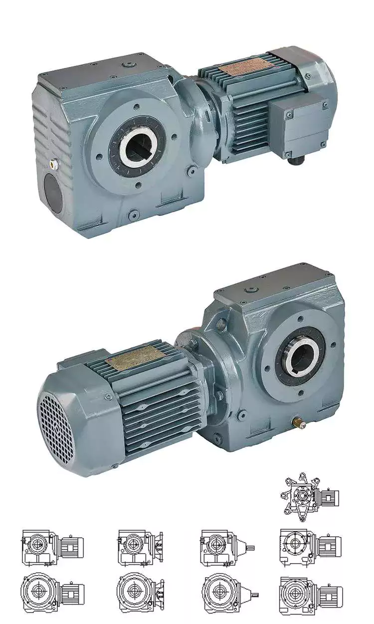
China Aluminum Housing Transmission Reduction Speed Reducer Gear Wheel Drive NMRV nmrv050 030 063 040 Worm Gearbox with Electric motor double enveloping worm gearbox

Warranty: 1 yr following vessel day
Relevant Industries: Creating Material Shops, Manufacturing Plant, Equipment Restore Shops, Foodstuff & Beverage Manufacturing facility, Farms, Printing Outlets, Strength & Mining, Construction operates
Bodyweight (KG): 10 KG, 10 KG
Tailored assistance: OEM, ODM
Gearing Arrangement: Worm
Output Torque: 2.6-1760N.m
Enter Pace: 750~3500rpm
Output Pace: fourteen-280rpm
Merchandise name: Gray shade worm reduction gearbox
Product: From RV25 up to RV185
Material: Aluminum&iron cating
Color: K9149 (Grey )OR RAL5571(blue)
Ratio: 7.5,ten,fifteen,20,thirty,forty,50,sixty,eighty,a hundred
Good quality Manage Program: ISO9001:2008
Port: ZheJiang or HangZhou Port,China

Merchandise Description Worm gearboxShell: aluminum alloy (foundation: 571-090) forged iron (base: 110-150) Worm: 20Cr metal. Carbonitriding treatment method (following fantastic grinding, keep the hardness of tooth surface HRC60, and the hardness thickness is better than .5mm) Worm gear: dress in-resistant nickel bronze with specific configuration The simple structure of RV series aluminum alloy worm equipment reducer is mostly composed of worm gear, ever-energy Very hot Sale Udl Series Infinite Sturdy Speed Variator Transmission Gearbox Pace Reducer shaft, bearing, box and its add-ons. It can be divided into 3 standard structural elements: box, worm gear, bearing and shaft mix. The box is the base of all the components in the worm gear reducer, and is an important accessory to help and fix the shafting elements, make certain the correct relative situation of the transmission equipment, and assistance the load performing on the reducer. Worm gear and worm are mainly used to transmit the movement and electrical power in between the 2 staggered shafts, whilst bearings and shafts are mainly employed to transmit electricity, operate and increase performance.Model: RV25 RV30 RV40 RV50 RV63 RV75 RV90 RV110 RV130 RV150 NMRV25 NMRV30 NMRV40 NMRV50 NMRV63 NMRV75 NMRV90 NMRV110 NMRV130 NMRV150 NRV25 NRV30 NRV40 NRV50 NRV63 NRV75 NRV90 NRV110 NRV130 NRV150Characteristic1. Compact mechanical construction, gentle volume and form, little dimensions and large efficiency2. Great warmth exchange performance and fast warmth dissipation3. Easy set up, flexibility, outstanding overall performance and straightforward maintenance4. Steady procedure, reduced sounds, durable5. Sturdy usability, large safety and trustworthiness

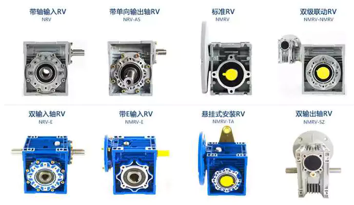
NMRVNRV…FNRV…VSNRV
NMRV…VSNMRV…FPC+NMRVNMRV+NMRV
For much more models, please contact us! Use and maintenance1. For the duration of installation, do not use pressure to the output elements and box of the reducer. For the duration of relationship, gasoline saw CZPT 5200cc for wooden slicing machine you should meet up with the corresponding needs for coaxiality and perpendicularity in between the device and the reducer.2. The lubricating oil shall be replaced when the reducer runs for four hundred hours initially, and the subsequent oil adjust interval is about 4000 hours.3. Sufficient lubricating oil shall be reserved in the reducer box and checked routinely.4. Pay interest to trying to keep the reducer appearance cleanse, and well timed remove dust and filth to facilitate heat dissipation Different motors can be matched according to your demands worm gearbox with Asynchronous motor worm gearbox with AC/DC motor worm gearbox with Stepping motor worm gearbox with Brushless motor Precautions for use of NMRV worm equipment reducer/RV reducer1. If the working setting of NMRV reducer is reduced than – 30 ℃ or greater than sixty-30 ℃, oil seals produced of specific materials must be replaced2. The motor matched with the NMRV reducer have to be suited for doing work in the lower temperature surroundings, and the motor energy should satisfy the torque demands when starting at low temperature3. The viscosity of lubricating oil will be increased prior to it is completely ready for use. The device should be loaded after no-load test operate to steer clear of gear failure4. When NMRV reducer is used for the first shutdown, change the lubricating oil after a hundred and fifty-four hundred hrs of operation, and the subsequent oil change reducer cycle is considerably less than or equivalent to 4000 hours5. Regularly verify the bodyweight and good quality of the oil, keep sufficient lubricating oil, and well timed replace the oil mixed with impurities or deteriorated. The working aspect of NMRV reducer depends on the true working surroundings. When selecting an appropriate service element, you need to think about the nature of the load at the output stop, the daily procedure time, the starting up frequency, and other factors. Other combination forms Pc+NMRV Worm gearbox NMRV+Computer+UDL+MOTOR NMRV+UDL+MOTOR Advocate Products Click on the solution in the picture to find out more! Manufacturing Method Certifications FAQ Q: Are you investing business or maker ?A: Our group is made up in 3 factories and 2 overseas revenue firms.Q: Do you provide samples ? is it totally free or added ?A: Indeed, we could offer you the sample for free cost but do not pay the cost of freight.Q: How prolonged is your supply time ? What is your phrases of payment ?A: Normally it is 40-forty five days. The time might differ dependent on the solution and the degree of customization. For normal items, the payment is: 30% T/T in progress ,stability prior to shippment.Q: What is the precise MOQ or value for your merchandise ?A: As an OEM business, we can provide and adapt our products to a extensive variety of requirements.As a result, MOQ and price tag may possibly tremendously differ with size, substance and additional requirements For occasion, Specialist tailored gear shaping hob manufacturing unit to map new style tailored substantial-top quality hob wholesale income expensive merchandise or regular goods will typically have a reduced MOQ. Make sure you make contact with us with all pertinent details to get the most precise quotation.If you have yet another question, make sure you truly feel cost-free to get in touch with us. Solution packaging

Advantages and disadvantages of worm gear reducer gearbox

If you are looking for a worm gear reducer gearbox, you have come to the right place. This article will cover the pros and cons of worm gear reducer gearboxes and discuss the different types available. You will learn about multi-head worm gear reducer gearboxes, hollow shaft worm gear reducer gearboxes as well as hypoid gear sets and motors.
worm reducer

Hollow shaft worm gear reducer gearbox

Hollow shaft worm gear reducer gearboxes are used to connect two or more rotating parts. They are available in single-axis and dual-axis versions and can be connected to various motor types. They can also have different ratios. The ratios of these gear reducer gearboxes depend on the quality of the bearings and assembly process.
Hollow shaft worm gear reducer gearboxes are made of bronze worm gears and cast iron hubs. The gears are lubricated with synthetic oil. They are lightweight and durable. They can be installed in various engine housings. Additionally, these gear reducer gearboxes are available in a variety of sizes. The range includes 31.5, 40, 50, 63, and 75mm models. Other sizes are available upon request.
In addition to worm gear reducer gearboxes, there are also helical gear reducer gearboxes. These reducer gearboxes can achieve very low output speeds. They are also suitable for all-around installations. In addition, the advantage of a multi-stage reducer gearbox is that it is more efficient than a single-stage gear reducer gearbox. They also feature low noise, low vibration, and low energy consumption.
Hollow shaft worm gear reducer gearboxes are generally less expensive and last longer. They are also a suitable replacement for solid shaft gearboxes for machines that require high torque without compromising strength. Typical gear arrangements include worm, spur, helical and bevel gears. Gear ratio is the ratio of input torque to output torque.

Multi-head worm gear reducer gearbox

The multi-head worm gear reducer gearbox is used to reduce the speed of the machine. It uses friction to hold the worm in place while transmitting power. These gears can also be called ground worms and hardened worm gears. They are useful in conveying systems and most engineering applications.
Multiple worm reducer gearboxes have a large number of gear ratios. These gear designs have a central cross-section that forms the front and rear boundaries of the worm gear. This design is a better choice than other worm gears because it is less prone to wear and can be used with a variety of motors and other electronics.
Adjustable multi-head worm gear reducer gearbox to reduce axial play. Usually, the backlash on the left and right sides of the worm is the same. However, if you need less backlash, you can buy a double lead worm gear. This design is ideal for precision applications requiring small clearances. The lead of the opposing teeth of the double worm gear is different from the right side, so the backlash can be adjusted without adjusting the center distance between the worm gears.
Worm gear reducer gearboxes are available from a variety of manufacturers. Many gear manufacturers stock these gears. Since the gear ratios are standardized, there is no need to adjust the height, diameter, or length of the shaft. Worm gears have fewer moving parts, which means they require less maintenance.
worm reducer

Hypoid Gear Set

Worm gears are the most common type of gear. While these gears are great for high-to-low ratios, hypoid gear sets are much more efficient in all ratios. This difference is due to higher torque density, better geometry and materials, and the way hypoid gears transmit force differently than worm gears.
Hypoid gear sets have curved helical teeth. This results in smooth gear meshing and little noise. This is because the hypoid gears start to slowly contact each other, but the contact progresses smoothly from tooth to tooth. This reduces friction and wears, thereby increasing the efficiency of the machine.
The main advantages of hypoid gears over worm gears are higher torque capacity and lower noise levels. Although their upfront cost may be higher, hypoid gears are more efficient than worm gears. They are able to handle higher initial inertia loads and can deliver more torque with a smaller motor. This saves money in the long run.
Another advantage of hypoid gears is the lower operating temperature. They also do not require oil lubrication or ventilation holes, reducing maintenance requirements. The hypoid gear set is maintenance-free, and the grease on the hypoid gear set lasts for decades.

Hypoid gear motor

A hypoid gear motor is a good choice for a worm gear reducer gearbox as it allows for a smaller motor and more efficient energy transfer. In fact, a 1 hp motor driving a hypoid reducer gearbox can provide the same output as a 1/2 hp motor driving a worm reducer gearbox. A study by Agknx compared two gear reduction methods and determined that a hypoid gear motor produces more torque and power than a worm reducer gearbox when using a fixed reduction ratio of 60:1. The study also showed that the 1/2 HP hypoid gear motor is more energy efficient and reduces electricity bills.
Worm reducer gearboxes run hotter than hypoid gears, and the added heat can shorten their lifespan. This can cause components to wear out faster, and the motor may require more frequent oil changes. In addition, hypoid gear motors are more expensive to manufacture.
Compared to worm gears, hypoid gears offer higher efficiency and lower operating noise. However, they require additional processing techniques. They are made of bronze, a softer metal capable of absorbing heavy shock loads. Worm drives require work hardening and are less durable. Operating noise is reduced by up to 30%, and hypoid gears are less prone to breakage than bevel gears.
Hypoid gear motors are prized for their efficiency and are used in applications requiring lower torque. A unique hypoid tooth profile reduces friction. In addition, hypoid gear motors are ideal for applications where space is limited. These geared motors are often used with pulleys and levers.

R series worm gear reducer gearbox

R series worm gear reducer gearboxes have a variety of characteristics that make them ideal for different applications. Its high rigidity cast iron housing and rigid side gears are designed for smooth drive and low noise. It also features high load capacity and long service life. Additionally, it can be assembled into many different configurations as required.
High efficiency, large output torque and good use efficiency. It comes in four basic models ranging from 0.12KW to 200KW. It can be matched with right angle bevel gearbox to provide large speed ratio and high torque. This combination is also suitable for low output and high torque.
worm reducer

AGKNX Electric Worm Gear reducer gearbox

AGKNX Electric worm gear reducer gearboxes are available with NEMA C-face mounting flanges for a variety of motors. These reducer gearboxes feature double lip oil seals, an aluminum alloy housing, and two bearings on the input and output shafts. These reducer gearboxes are rust-proof and have epoxy paint on the inside. They are available in a variety of ratios, from 7.5:1 to 100:1.
Worm reducer gearboxes are one of the most cost-effective and compact gears. These reducer gearboxes increase output torque while reducing input speed. AGKNX Electric’s worm gear reducer gearboxes are pre-installed with Mobil SHC634 Synthetic Gear Oil. These reducer gearboxes have an internal oil gallery guide to protect the shaft. They also have a one-piece cast iron housing.
AGKNX Electric Corporation is the leading independent distributor of electric motors in the United States. They have eight strategically located warehouses, enabling them to ship most orders on the same day. They offer motors of various sizes up to 20,000 hp. They also offer a variety of motor controls and variable speed drives.
China Aluminum Housing Transmission Reduction Speed Reducer Gear Wheel Drive NMRV nmrv050 030 063 040 Worm Gearbox with Electric motor     double enveloping worm gearboxChina Aluminum Housing Transmission Reduction Speed Reducer Gear Wheel Drive NMRV nmrv050 030 063 040 Worm Gearbox with Electric motor     double enveloping worm gearbox
editor by czh 2023-02-09

China Low noise small engine reduction speed reducer stepper motor 90 degree RV030 RV040 RV050 RV063 worm gearbox double stage worm gearbox

Relevant Industries: Developing Substance Shops, Manufacturing Plant, Equipment Restore Retailers, Foods & Beverage Manufacturing unit, Farms, Printing Retailers, Building works , Power & Mining, Meals & Beverage Retailers, Other
Weight (KG): 2 KG
Personalized assist: OEM, ODM, OBM
Gearing Arrangement: Worm
Output Torque: 2.6-1760N.m
Enter Speed: 750~3500rpm
Output Pace: fourteen-280rpm
Merchandise title: Gray color worm reduction gearbox
Design: From RV25 up to RV185
Substance: Aluminum&iron cating
Color: K9149 (Gray )OR RAL5571(blue)
Ratio: 7.5,ten,15,20,30,forty,50,sixty,80,100
Guarantee: 1 yr after vessel date
Good quality Handle Method: ISO9001:2008
Port: ZheJiang or HangZhou Port,China

Goods Description

TypeWorm Equipment Velocity Reducer/ gearbox
ModelWMRV twenty five/thirty/40/fifty/sixty three/seventy five/90/one hundred ten/130/150/185
Ratio7.5,10,15,twenty,twenty five,30,40,fifty,sixty,eighty,100.
ColorBlue(RAL5571)/Silver grey (K9149) Or On Customer Request
MaterialAluminum alloy
Worm wheel: Aluminum Bronze or Zinc Bronze
Worm shaft: 20CrMn Ti
Output Shaft: metal-45#
PackingCarton, Honey Comb Carton, Wooden Scenario with picket pallet
Warranty1 12 months
Input Power0.09kw,.18kw,1.1KW,1.5KW,2.2KW,3KW,4KW,5.5KW,7.5KW,11Kw and so on.
UsagesIndustrial Machine: Foodstuff Things, Ceramics, CHEMICAL, Packing, Dyeing,Wooden working, Glass.
IEC FlangeIEC normal flange or on customer request
LubricantSynthetic oil or worm gear oil
A lot more Goods Company Profile Item Line Certifications Exhibition Buyer Testimonials FAQ 1. How to pick a gearbox which fulfills our need?You can refer to our catalogue to select the gearbox or we can assist to pick when you providethe technical details of essential output torque, output speed and motor parameter and so forth.2. What data shall we give prior to putting a purchase purchase?a) Variety of the gearbox, ratio, enter and output kind, input flange, mounting place, and motor informationetc.b) Housing color.c) Acquire quantity.d) Other particular needs.3. What industries are your gearboxes being utilised?Our gearboxes are extensively employed in the regions of textile, foods processing, beverage, chemical business,escalator,automatic storage gear, metallurgy, tabacco, environmental safety, logistics and and so forth.

Key Market Insights Related to Worm Reduction Gearboxes

A gearbox is a mechanical device that allows you to shift between different speeds or gears. It does so by using one or more clutches. Some gearboxes are single-clutch, while others use two clutches. You can even find a gearbox with closed bladders. These are also known as dual clutches and can shift gears more quickly than other types. Performance cars are designed with these types of gearboxes.
gearbox

Backlash measurement

Gearbox backlash is a common component that can cause noise or other problems in a car. In fact, the beats and sets of gears in a gearbox are often excited by the oscillations of the engine torque. Noise from gearboxes can be significant, particularly in secondary shafts that engage output gears with a differential ring. To measure backlash and other dimensional variations, an operator can periodically take the output shaft’s motion and compare it to a known value.
A comparator measures the angular displacement between two gears and displays the results. In one method, a secondary shaft is disengaged from the gearbox and a control gauge is attached to its end. A threaded pin is used to secure the differential crown to the secondary shaft. The output pinion is engaged with the differential ring with the aid of a control gauge. The angular displacement of the secondary shaft is then measured by using the dimensions of the output pinion.
Backlash measurements are important to ensure the smooth rotation of meshed gears. There are various types of backlash, which are classified according to the type of gear used. The first type is called circumferential backlash, which is the length of the pitch circle around which the gear rotates to make contact. The second type, angular backlash, is defined as the maximum angle of movement between two meshed gears, which allows the other gear to move when the other gear is stationary.
The backlash measurement for gearbox is one of the most important tests in the manufacturing process. It is a criterion of tightness or looseness in a gear set, and too much backlash can jam a gear set, causing it to interface on the weaker part of its gear teeth. When backlash is too tight, it can lead to gears jamming under thermal expansion. On the other hand, too much backlash is bad for performance.

Worm reduction gearboxes

Worm reduction gearboxes are used in the production of many different kinds of machines, including steel and power plants. They are also used extensively in the sugar and paper industries. The company is constantly aiming to improve their products and services to remain competitive in the global marketplace. The following is a summary of key market insights related to this type of gearbox. This report will help you make informed business decisions. Read on to learn more about the advantages of this type of gearbox.
Compared to conventional gear sets, worm reduction gearboxes have few disadvantages. Worm gear reducers are commonly available and manufacturers have standardized their mounting dimensions. There are no unique requirements for shaft length, height, and diameter. This makes them a very versatile piece of equipment. You can choose to use one or combine several worm gear reducers to fit your specific application. And because they have standardized ratios, you will not have to worry about matching up multiple gears and determining which ones fit.
One of the primary disadvantages of worm reduction gearboxes is their reduced efficiency. Worm reduction gearboxes usually have a maximum reduction ratio of five to sixty. The higher-performance hypoid gears have an output speed of around ten to twelve revolutions. In these cases, the reduced ratios are lower than those with conventional gearing. Worm reduction gearboxes are generally more efficient than hypoid gear sets, but they still have a low efficiency.
The worm reduction gearboxes have many advantages over traditional gearboxes. They are simple to maintain and can work in a range of different applications. Because of their reduced speed, they are perfect for conveyor belt systems.
gearbox

Worm reduction gearboxes with closed bladders

The worm and the gear mesh with each other in a combination of sliding and rolling movements. This sliding action is dominant at high reduction ratios, and the worm and gear are made of dissimilar metals, which results in friction and heat. This limits the efficiency of worm gears to around thirty to fifty percent. A softer material for the gear can be used to absorb shock loads during operation.
A normal gear changes its output independently once a sufficient load is applied. However, the backstop complicates the gear configuration. Worm gears require lubrication because of the sliding wear and friction introduced during movement. A common gear arrangement moves power at the peak load section of a tooth. The sliding happens at low speeds on either side of the apex and occurs at a low velocity.
Single-reduction gearboxes with closed bladders may not require a drain plug. The reservoir for a worm gear reducer is designed so that the gears are in constant contact with lubricant. However, the closed bladders will cause the worm gear to wear out more quickly, which can cause premature wear and increased energy consumption. In this case, the gears can be replaced.
Worm gears are commonly used for speed reduction applications. Unlike conventional gear sets, worm gears have higher reduction ratios. The number of gear teeth in the worm reduces the speed of a particular motor by a substantial amount. This makes worm gears an attractive option for hoisting applications. In addition to their increased efficiency, worm gears are compact and less prone to mechanical failure.

Shaft arrangement of a gearbox

The ray-diagram of a gearbox shows the arrangement of gears in the various shafts of the transmission. It also shows how the transmission produces different output speeds from a single speed. The ratios that represent the speed of the spindle are called the step ratio and the progression. A French engineer named Charles Renard introduced five basic series of gearbox speeds. The first series is the gear ratio and the second series is the reverse gear ratio.
The layout of the gear axle system in a gearbox relates to its speed ratio. In general, the speed ratio and the centre distance are coupled by the gear axles to form an efficient transmission. Other factors that may affect the layout of the gear axles include space constraints, the axial dimension, and the stressed equilibrium. In October 2009, the inventors of a manual transmission disclosed the invention as No. 2. These gears can be used to realize accurate gear ratios.
The input shaft 4 in the gear housing 16 is arranged radially with the gearbox output shaft. It drives the lubricating oil pump 2. The pump draws oil from a filter and container 21. It then delivers the lubricating oil into the rotation chamber 3. The chamber extends along the longitudinal direction of the gearbox input shaft 4, and it expands to its maximum diameter. The chamber is relatively large, due to a detent 43.
Different configurations of gearboxes are based on their mounting. The mounting of gearboxes to the driven equipment dictates the arrangement of shafts in the gearbox. In certain cases, space constraints also affect the shaft arrangement. This is the reason why the input shaft in a gearbox may be offset horizontally or vertically. However, the input shaft is hollow, so that it can be connected to lead through lines or clamping sets.
gearbox

Mounting of a gearbox

In the mathematical model of a gearbox, the mounting is defined as the relationship between the input and output shafts. This is also known as the Rotational Mount. It is one of the most popular types of models used for drivetrain simulation. This model is a simplified form of the rotational mount, which can be used in a reduced drivetrain model with physical parameters. The parameters that define the rotational mount are the TaiOut and TaiIn of the input and output shaft. The Rotational Mount is used to model torques between these two shafts.
The proper mounting of a gearbox is crucial for the performance of the machine. If the gearbox is not aligned properly, it may result in excessive stress and wear. It may also result in malfunctioning of the associated device. Improper mounting also increases the chances of the gearbox overheating or failing to transfer torque. It is essential to ensure that you check the mounting tolerance of a gearbox before installing it in a vehicle.

China Low noise small engine reduction speed reducer stepper motor 90 degree RV030 RV040 RV050 RV063 worm gearbox     double stage worm gearboxChina Low noise small engine reduction speed reducer stepper motor 90 degree RV030 RV040 RV050 RV063 worm gearbox     double stage worm gearbox
editor by czh

China Professional DM-95SS545 95mm custom 12v 24v metal dc spur gear 3000rpm 50kgcm micro 90 degree reduction gearbox motor with reductor wholesaler

Warranty: 6 months
Applicable Industries: Hotels, Garment Shops, Building Material Shops, Manufacturing Plant, Machinery Repair Shops, Food & Beverage Factory, Farms, Restaurant, Home Use, Retail, Food Shop, Printing Shops, Construction works , Energy & Mining, Food & Beverage Shops, Forklift Brush Dc Series Motor 72v 6.3kw XQ-6.3 For Electric Car Other, Advertising Company
Customized support: OEM, ODM, JDM
Gearing Arrangement: Spur
Output Torque: 2~50kgf.cm
Input Speed: 2000~9000rpm
Output Speed: 2~100rpm
Working Current: 0.2~2A
Gearbox Size: 95*68*H16mm
Stall Torque: 10kgf.cm-150kgf.cm
Driving Motor Speed: 2000rpm-9000rpm
Gears Style: Metal gear
Shaft diameter: 10mm
Normal Shaft Length: 15mm
Certification: CE, Rohs, CE
Application: door lock, robotic
Working Hours: 500-800 hours
Packaging Details: Foam packed with outer paper cartons

Products Description Appearance size: Products Specification Gearbox Data:

Number of stages
3
4
5

Reduction ratio
94
394
1166

Gearbox length “L”mm
16
16
16

Breaking torque(kgf.cm)
15
60
120

Gearbox efficiency
73%
65%
59%

Driving Motor Data:

Motor model
RatedVolt.
No load

Load

Stall

Current
Speed
Current
Speed
Torque
Outputpower
Torque
Current

V
mA
r/min
mA
r/min
gf.cm
W
gf.cm
mA

DM-545-012-3000
12
≤110
3000
≤450
2200
100
2.3
≥320
≥1440

DM-545-012-4500
12
≤220
4500
≤800
3300
150
5.1
≥ Heavy duty nonstandard stainless steel industrial conveyor large pitch roller chain 480
≥2400

DM-545-012-6000
12
≤350
6000
≤1500
4500
200
9.2
≥640
≥4400

DM-545-571-3000
24
≤60
3000
≤230
2200
100
2.3
≥320
≥720

DM-545-571-4500
24
≤110
4500
≤400
3300
150
5.1
≥480
≥1200

DM-545-571-6000
24
≤150
6000
≤ Manufacturer OEM Iron nickel plated carbon steel pin flex putter front drive shaft 750
4500
200
9.2
≥640
≥2400

Gear Motor Data:

Motor model
RatedVolt.
No load

Load

Stall

Current
Speed
Current
Speed
Torque
Output power
Torque
Current

V
A
r/min
A
r/min
kgf.cm
W
kgf.cm
A

DM-95SS5450 0571 00-94K
6.0
0.68
62.0
2.88
48.9
14.7
7.38
69.5
11.09

DM-95SS5450126000-94K
12.0
0.24
62.5
1.36
53.0
15.0
8.59
104.0
7.67

DM-95SS5455714500-394K
24.0
0.11
11.3
0.48
9.1
52.0
4.93
274.0
2.04

HangZhou Xihu (West Lake) Dis.ming Motor Co., Ltd. is specialized in designing, manufacturing and selling micro DC motors, especially gear motors.We have successfully worked out over 100 series of micro DC motors. Our products are widely applied in household appliances,audio/video products, office equipment, health-care and beauty-care facilities, medical appliances, high-class toys, electronictools, electronic commodity, automotive parts and automatic systems.We have a team of professional staff who are working on R&Dand QC. They ensure our good quality managing system and advance technology.

Choosing a Gearbox For Your Application

The gearbox is an essential part of bicycles. It is used for several purposes, including speed and force. A gearbox is used to achieve one or both of these goals, but there is always a trade-off. Increasing speed increases wheel speed and forces on the wheels. Similarly, increasing pedal force increases the force on the wheels. This makes it easier for cyclists to accelerate their bicycles. However, this compromise makes the gearbox less efficient than an ideal one.
gearbox

Dimensions

Gearboxes come in different sizes, so the size of your unit depends on the number of stages. Using a chart to determine how many stages are required will help you determine the dimensions of your unit. The ratios of individual stages are normally greater at the top and get smaller as you get closer to the last reduction. This information is important when choosing the right gearbox for your application. However, the dimensions of your gearbox do not have to be exact. Some manufacturers have guides that outline the required dimensions.
The service factor of a gearbox is a combination of the required reliability, the actual service condition, and the load that the gearbox will endure. It can range from 1.0 to 1.4. If the service factor of a gearbox is 1.0, it means that the unit has just enough capacity to meet your needs, but any extra requirements could cause the unit to fail or overheat. However, service factors of 1.4 are generally sufficient for most industrial applications, since they indicate that a gearbox can withstand 1.4 times its application requirement.
Different sizes also have different shapes. Some types are concentric, while others are parallel or at a right angle. The fourth type of gearbox is called shaft mount and is used when mounting the gearbox by foot is impossible. We will discuss the different mounting positions later. In the meantime, keep these dimensions in mind when choosing a gearbox for your application. If you have space constraints, a concentric gearbox is usually your best option.

Construction

The design and construction of a gearbox entails the integration of various components into a single structure. The components of a gearbox must have sufficient rigidity and adequate vibration damping properties. The design guidelines note the approximate values for the components and recommend the production method. Empirical formulas were used to determine the dimensions of the various components. It was found that these methods can simplify the design process. These methods are also used to calculate the angular and axial displacements of the components of the gearbox.
In this project, we used a 3D modeling software called SOLIDWORKS to create a 3-D model of a gear reducer. We used this software to simulate the structure of the gearbox, and it has powerful design automation tools. Although the gear reducer and housing are separate parts, we model them as a single body. To save time, we also removed the auxiliary elements, such as oil inlets and oil level indicators, from the 3D model.
Our method is based on parameter-optimized deep neural networks (DBNs). This model has both supervised and unsupervised learning capabilities, allowing it to be self-adaptive. This method is superior to traditional methods, which have poor self-adaptive feature extraction and shallow network generalization. Our algorithm is able to recognize faults in different states of the gearbox using its vibration signal. We have tested our model on two gearboxes.
With the help of advanced material science technologies, we can now manufacture the housing for the gearbox using high-quality steel and aluminium alloys. In addition, advanced telematics systems have increased the response time of manufacturers. These technologies are expected to create tremendous opportunities in the coming years and fuel the growth of the gearbox housing market. There are many different ways to construct a gearbox, and these techniques are highly customizable. In this study, we will consider the design and construction of various gearbox types, as well as their components.
gearbox

Working

A gearbox is a mechanical device that transmits power from one gear to another. The different types of gears are called planetary gears and are used in a variety of applications. Depending on the type of gearbox, it may be concentric, parallel, or at a right angle. The fourth type of gearbox is a shaft mount. The shaft mount type is used in applications that cannot be mounted by foot. The various mounting positions will be discussed later.
Many design guidelines recommend a service factor of 1.0, which needs to be adjusted based on actual service conditions. This factor is the combined measure of external load, required reliability, and overall gearbox life. In general, published service factors are the minimum requirements for a particular application, but a higher value is necessary for severe loading. This calculation is also recommended for high-speed gearboxes. However, the service factor should not be a sole determining factor in the selection process.
The second gear of a pair of gears has more teeth than the first gear. It also turns slower, but with greater torque. The second gear always turns in the opposite direction. The animation demonstrates this change in direction. A gearbox can also have more than one pair of gears, and a first gear may be used for the reverse. When a gear is shifted from one position to another, the second gear is engaged and the first gear is engaged again.
Another term used to describe a gearbox is “gear box.” This term is an interchangeable term for different mechanical units containing gears. Gearboxes are commonly used to alter speed and torque in various applications. Hence, understanding the gearbox and its parts is essential to maintaining your car’s performance. If you want to extend the life of your vehicle, be sure to check the gearbox’s efficiency. The better its functioning, the less likely it is to fail.

Advantages

Automatic transmission boxes are almost identical to mechanical transmission boxes, but they also have an electronic component that determines the comfort of the driver. Automatic transmission boxes use special blocks to manage shifts effectively and take into account information from other systems, as well as the driver’s input. This ensures accuracy and positioning. The following are a few gearbox advantages:
A gearbox creates a small amount of drag when pedaling, but this drag is offset by the increased effort to climb. The external derailleur system is more efficient when adjusted for friction, but it does not create as little drag in dry conditions. The internal gearbox allows engineers to tune the shifting system to minimize braking issues, pedal kickback, and chain growth. As a result, an internal gearbox is a great choice for bikes with high-performance components.
Helical gearboxes offer some advantages, including a low noise level and lower vibration. They are also highly durable and reliable. They can be extended in modular fashion, which makes them more expensive. Gearboxes are best for applications involving heavy loads. Alternatively, you can opt for a gearbox with multiple teeth. A helical gearbox is more durable and robust, but it is also more expensive. However, the benefits far outweigh the disadvantages.
A gearbox with a manual transmission is often more energy-efficient than one with an automatic transmission. Moreover, these cars typically have lower fuel consumption and higher emissions than their automatic counterparts. In addition, the driver does not have to worry about the brakes wearing out quickly. Another advantage of a manual transmission is its affordability. A manual transmission is often available at a lower cost than its automatic counterpart, and repairs and interventions are easier and less costly. And if you have a mechanical problem with the gearbox, you can control the fuel consumption of your vehicle with appropriate driving habits.
gearbox

Application

While choosing a gearbox for a specific application, the customer should consider the load on the output shaft. High impact loads will wear out gear teeth and shaft bearings, requiring higher service factors. Other factors to consider are the size and style of the output shaft and the environment. Detailed information on these factors will help the customer choose the best gearbox. Several sizing programs are available to determine the most appropriate gearbox for a specific application.
The sizing of a gearbox depends on its input speed, torque, and the motor shaft diameter. The input speed must not exceed the required gearbox’s rating, as high speeds can cause premature seal wear. A low-backlash gearbox may be sufficient for a particular application. Using an output mechanism of the correct size may help increase the input speed. However, this is not recommended for all applications. To choose the right gearbox, check the manufacturer’s warranty and contact customer service representatives.
Different gearboxes have different strengths and weaknesses. A standard gearbox should be durable and flexible, but it must also be able to transfer torque efficiently. There are various types of gears, including open gearing, helical gears, and spur gears. Some of the types of gears can be used to power large industrial machines. For example, the most popular type of gearbox is the planetary drive gearbox. These are used in material handling equipment, conveyor systems, power plants, plastics, and mining. Gearboxes can be used for high-speed applications, such as conveyors, crushers, and moving monorail systems.
Service factors determine the life of a gearbox. Often, manufacturers recommend a service factor of 1.0. However, the actual value may be higher or lower than that. It is often useful to consider the service factor when choosing a gearbox for a particular application. A service factor of 1.4 means that the gearbox can handle 1.4 times the load required. For example, a 1,000-inch-pound gearbox would need a 1,400-inch-pound gearbox. Service factors can be adjusted to suit different applications and conditions.

China Professional DM-95SS545 95mm custom 12v 24v metal dc spur gear 3000rpm 50kgcm micro 90 degree reduction gearbox motor with reductor  wholesaler China Professional DM-95SS545 95mm custom 12v 24v metal dc spur gear 3000rpm 50kgcm micro 90 degree reduction gearbox motor with reductor  wholesaler